Article

A Model-Based Engineering Methodology and Architecture for Resilience in Systems-of-Systems: A Case of Water Supply Resilience to Flooding

1
Advanced VR Research Centre, Loughborough University, Loughborough, Leicestershire LE11 3TU, UK
2
School of Water, Energy and Environment, Cranfield University, Cranfield, Bedfordshire MK43 0AL, UK
3
Centre for Water Systems, College of Engineering, Mathematics and Physical Sciences, University of Exeter, Exeter, Devon EX4 4QF, UK
*
Author to whom correspondence should be addressed.
Water 2019, 11(3), 496; https://doi.org/10.3390/w11030496
Submission received: 5 February 2019 / Revised: 25 February 2019 / Accepted: 3 March 2019 / Published: 8 March 2019
(This article belongs to the Special Issue Flood Risk and Resilience)

Abstract

:
There is a clear and evident requirement for a conscious effort to be made towards a resilient water system-of-systems (SoS) within the UK, in terms of both supply and flooding. The impact of flooding goes beyond the immediately obvious socio-aspects of disruption, cascading and affecting a wide range of connected systems. The issues caused by flooding need to be treated in a fashion which adopts an SoS approach to evaluate the risks associated with interconnected systems and to assess resilience against flooding from various perspectives. Changes in climate result in deviations in frequency and intensity of precipitation; variations in annual patterns make planning and management for resilience more challenging. This article presents a verified model-based system engineering methodology for decision-makers in the water sector to holistically, and systematically implement resilience within the water context, specifically focusing on effects of flooding on water supply. A novel resilience viewpoint has been created which is solely focused on the resilience aspects of architecture that is presented within this paper. Systems architecture modelling forms the basis of the methodology and includes an innovative resilience viewpoint to help evaluate current SoS resilience, and to design for future resilient states. Architecting for resilience, and subsequently simulating designs, is seen as the solution to successfully ensuring system performance does not suffer, and systems continue to function at the desired levels of operability. The case study presented within this paper demonstrates the application of the SoS resilience methodology on water supply networks in times of flooding, highlighting how such a methodology can be used for approaching resilience in the water sector from an SoS perspective. The methodology highlights where resilience improvements are necessary and also provides a process where architecture solutions can be proposed and tested.

1. Introduction

Water is essential to people, businesses and the environment. The sustainability of water resources is fundamental to life as we know it and access to clean water is essential to society. A generalised depiction (rich picture [1]) of the water “system-of-systems” (SoS) can be seen in Figure 1, which illustrates the complexity and high-level connectivity between stakeholders and constituent systems. An SoS is a large set of interconnected systems which collaborate to bring about behaviours and capabilities greater than the sum of the individual parts.
Climate projections (UKP09) [2] suggest that the change in climate [3] and the rise in demand for water will increase the strain on UK water resources. General trend projections indicate warmer and drier summers that will result in less water being available for all uses in the coming decades. Additionally, what is expected is that winters will generally be wetter with heavier downpours of rain which will increase the risk of flooding [4]. To this end, the water needs of the UK population, industry and associated dependencies is expected to increase due to forecast population growth [5].
The risks posed by flooding on supply water to demand points ought to be considered just as much as the immediately obvious and devastating impact flooding has on the lives of people, buildings and the environment. This would imply that water is successfully supplied to all demand regions (domestic, industrial and agricultural) whatever the circumstances are of the environment and that the water SoS holistically demonstrates levels of resilience in different operational scenarios. This entails both the aforementioned scenario of less water availability and increased temperatures, and also in crisis scenarios such as natural and man-made disasters, where water may become unavailable or available only at a depleted level, for a certain period of time. Therefore, when attempting to “engineer resilience” [6,7] into such systems, there needs to be an understanding of levels of performance, acceptable levels of performance, and also recovery strategies to mitigate against loss of service.
The objective of this paper is to demonstrate how the resilience methodology created can explore where resilience improvements are necessary and then increase the resilience of water supply systems during times of flooding, by adopting an SoS-based approach and applied model-based processes. A key contribution is the inclusion of a resilience viewpoint within an existing architecture framework to allow engineers to model certain aspects of SoS resilience using different views and model types.

1.1. Resilience in the Water Sector

‘Resilience’ is a term that has been used for a long time and in many different domains [6,8,9]. The popularity of the concept is currently on the rise [10] and has attracted great interest from engineers [11] and safety analysts [12] alike. Many variations of the definition exist but the core connotation remains constant with the Latin origin of the word “resilire”, to spring back or rebound [13] i.e., to recover. Traditionally, resilience has been closely linked with safety and risk management strategy planning, taking a hindsight and “lessons-learnt” approach from past incidents to improve existing and future systems. For knowledge purposes, there are many advantages in studying past failures and disasters to gain an insight into why things go wrong, how response systems performed, taking the positives and negatives from a given instance to inform better decision-making in the future. That said, a more effective approach is a proactive one, to test possible future scenarios and see how the system would respond, in order to develop systems with the capability to deal with change prior to an incident and mitigating the severity of the potential impact.
For the purpose of this research, the water system and the occurrence of a flooding event was considered as a system-of-systems (SoS) [14] as a means to appreciate the complexity of water supply systems and associate systems in times of flooding. This permitted the development of model-based methodology and to propose methods to design future phases of water systems that ensure resilience strategies are included early on in their lifecycle phases. In this specific case, the methodology supports increasing the overall resilience of the systems delivering water to consumers in times of flooding.
Literature shows resilience frameworks being developed from an “adaptation” perspective [14] which is interesting from the standpoint of existing infrastructure having to cope with new threats. Nelson et al. [14] provide a definition for systems which are resilient as being able to “undergo change and still retain the same function and structure while maintaining the options to develop.” This suggests that systems are able to support a degraded level of performance and provide the core functions required to meet the system’s goals. The notion of “surprises” is introduced by Hollangel [15] in his definition of resilience which suggests the idea of unanticipated events, making the challenge for engineering for certain types of events more difficult because they are less predictable. Certain definitions highlight the importance of time and costs whilst a system is in the recovery stages of an incident [16] and the significance of reducing these as optimally as possible. With all definitions, the implications of resilience are all context dependent, therefore defining what is meant by resilient in any given scenario is a critical part of engineering for resilience. This is equally true in our scenario of continuing the supply of water during extreme weather events like flooding. Legacy systems (pumps, for example) may not be able to cope with the changes in flood frequency and flood severity, and evolutions to existing systems should to be made, say by replacing aging systems, ensuring sustainability in the UK’s water supply SoS.
The concept of resilience in this instance would attempt to mitigate against this risk of failure and to ensure the availability of water, even in times of severe conditions, i.e., infrastructure resilience. The resilience curve [17,18] is a common representation of the responsiveness of a system to undergo a disturbance and to recover from it in terms of performance; it has four main stages; reliability, unreliability, recovery, and, recovered steady state [8], as seen in Figure 2a.
The objective when considering the resilience of the water system, and the constituent systems which enable the supply of water is that when the occurrence of a flood for example occurs, then the resilience curve is more like profile (i) in Figure 2b, than profile (ii). Profile (ii) shows complete failure of the system and recovers to a state that is substantially below its original level. Where ideally, there would be no loss in performance, however profile (i) shows an “acceptable loss” in performance, and a full recovery to its normal operational state over a period of time. Of course, this is context dependent, but describing the system resilience in this way enables engineers and architects to apply the resilience methodology and test future designs against variables which are of importance.
Having a succinct methodology which enables engineers, architects and decision makers in the water domain to assess the resilience of current systems, and to then propose and test future architectural designs would be invaluable. The methodology which has been created within this article demonstrates a workflow which defines the scope of interest, and then models the elements within a reference architecture using systems modelling languages and architecture frameworks. Additionally, these static architectures can be examined by migrating them into simulation environments to assess their performance. Favourably, alternative designs and architectures can be modelled, simulated and tested to see which provides the most resilient solutions in terms of water availability and continual supply.
The value of adding the resilience viewpoint within the methodology is to specifically address aspects of resilience like criticality and vulnerability between certain nodes of the network and to identify key risks in certain scenarios. This allows the architect to think about strategies which enable the operational systems to mitigate against certain incidents and remain reliable and resilient at all times. Assigning metrics to individual constituents within a system is seen to be a step in the right direction for developing a set of metrics to measure the resilience in the water sector. This is seen to be another feature of the resilience viewpoint, an ongoing development process and research initiative.

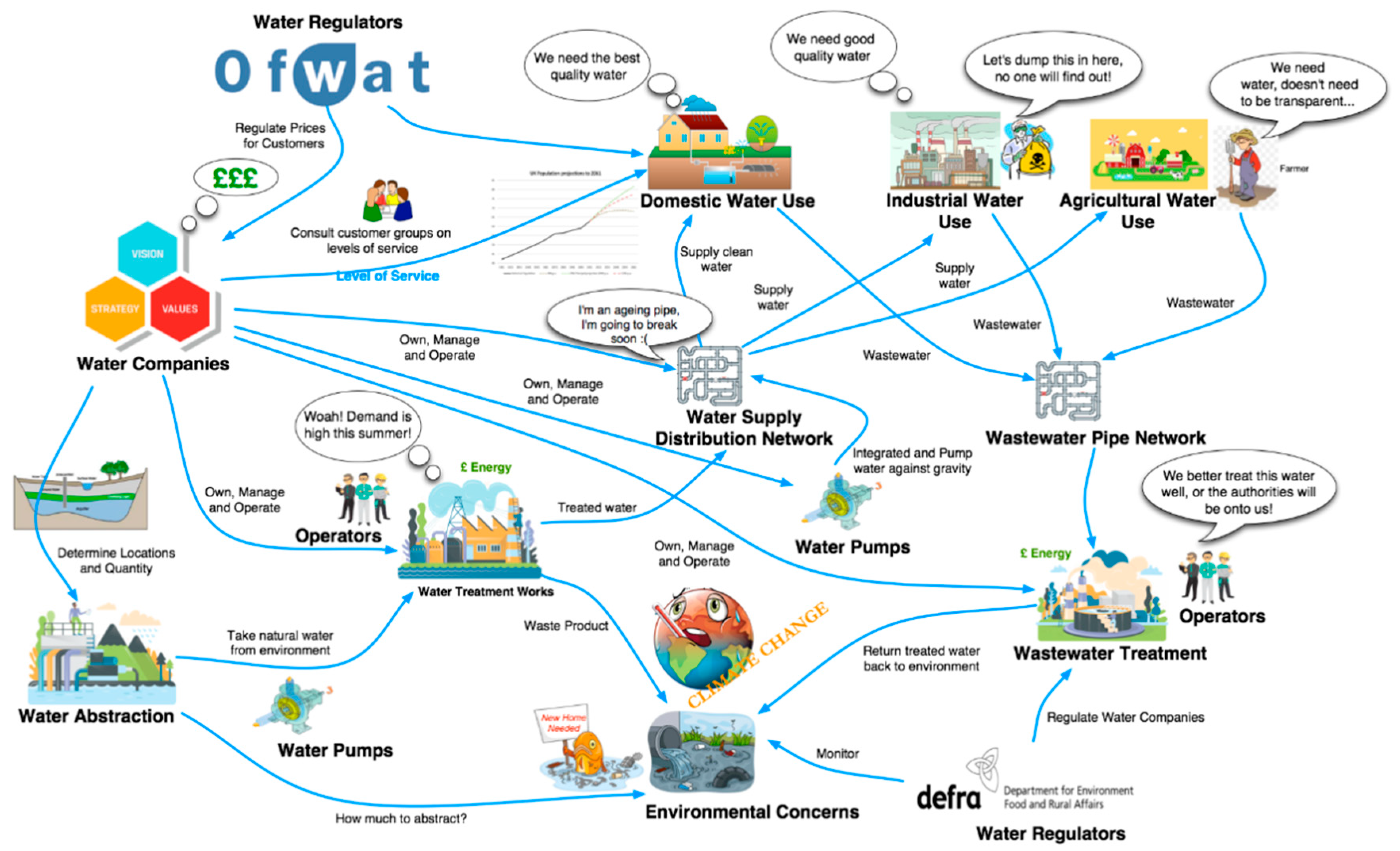
1.2. Systems-of-Systems (SoS) in the Context of Water Supply/Flooding

Several definitions of what constitutes an SoS have been provided by Jamshidi 2005, 2008 [19], though the most favourable definition from the book is “systems of systems are large-scale integrated systems that are heterogeneous and independently operable on their own, but are networked together for a common goal,” [20]. Maier [21,22] claimed that the term ‘system-of-systems’ did not have a distinct and recognised definition, although he did acknowledge that the SoS idea is widely accepted and generally recognised. He cited a number of examples such as integrated air defence networks, the internet, intelligent transport systems, and enterprise information networks, which are an emergent class of systems comprising large-scale systems in their own right. This has led to the categorisation of an SoS into five important characteristics:
  • Operational independence of the elements: The constituent systems (CSs) can operate independently.
  • Managerial independence of the elements: The constituent systems are acquired separately by different managerial entities.
  • Evolutionary development: An SoS evolves over time, developing its capabilities as the constituent systems are changed, added or removed.
  • Emergent behaviour: The SoS itself offers additional services above and beyond the capabilities of the constituent systems. However, it can also exhibit unexpected and potentially damaging behaviours.
  • Geographic distribution: The geographic extent of the constituent systems is large.
Accordingly, a definition of resilience has been created by the authors in the context of SoS, such as that of the water supply system, which is of topic in this case; “The dynamic ability of the SoS to re-adjust and recover when faced with change and disruption, at both the SoS and constituent system level. To continue to provide operational capacity at a certain level of (degraded) functionality and performance.”
There is a clear and evident requirement for a conscious effort to be made towards a resilient water SoS within the UK, in terms of both supply and in terms of flooding. This effort is as stated, an ‘SoS-wide’ effort which must be supported by a range of stakeholders, including; water companies, emergency response agencies, wastewater companies, regulators, and consumers of water, to name a few. Natural disasters (including flooding) increase the probability of the water infrastructure being damaged which also could jeopardize the supply of water to customers of all types (domestic, industry, agriculture).

2. Materials and Methods

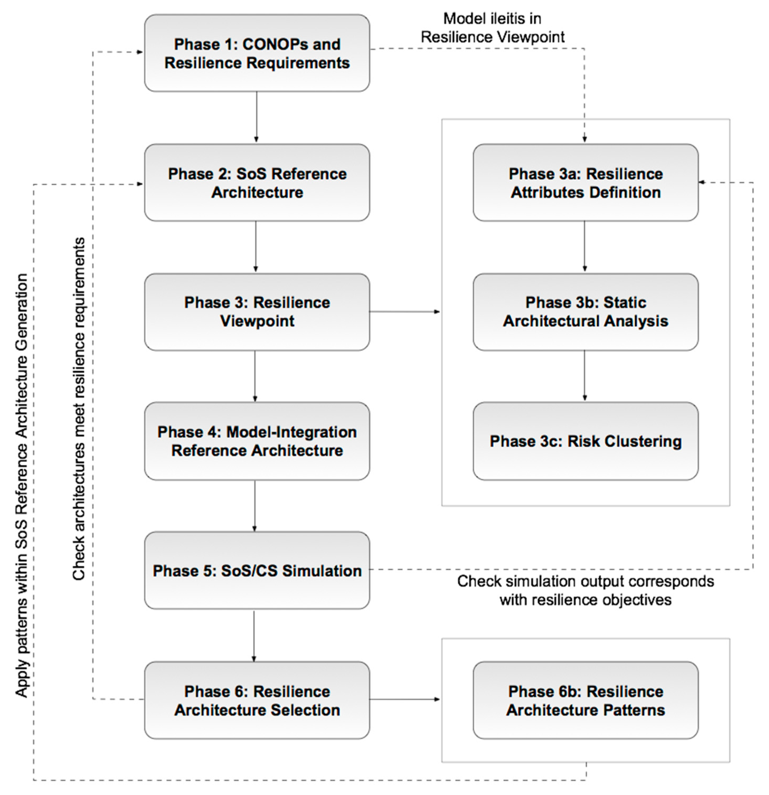
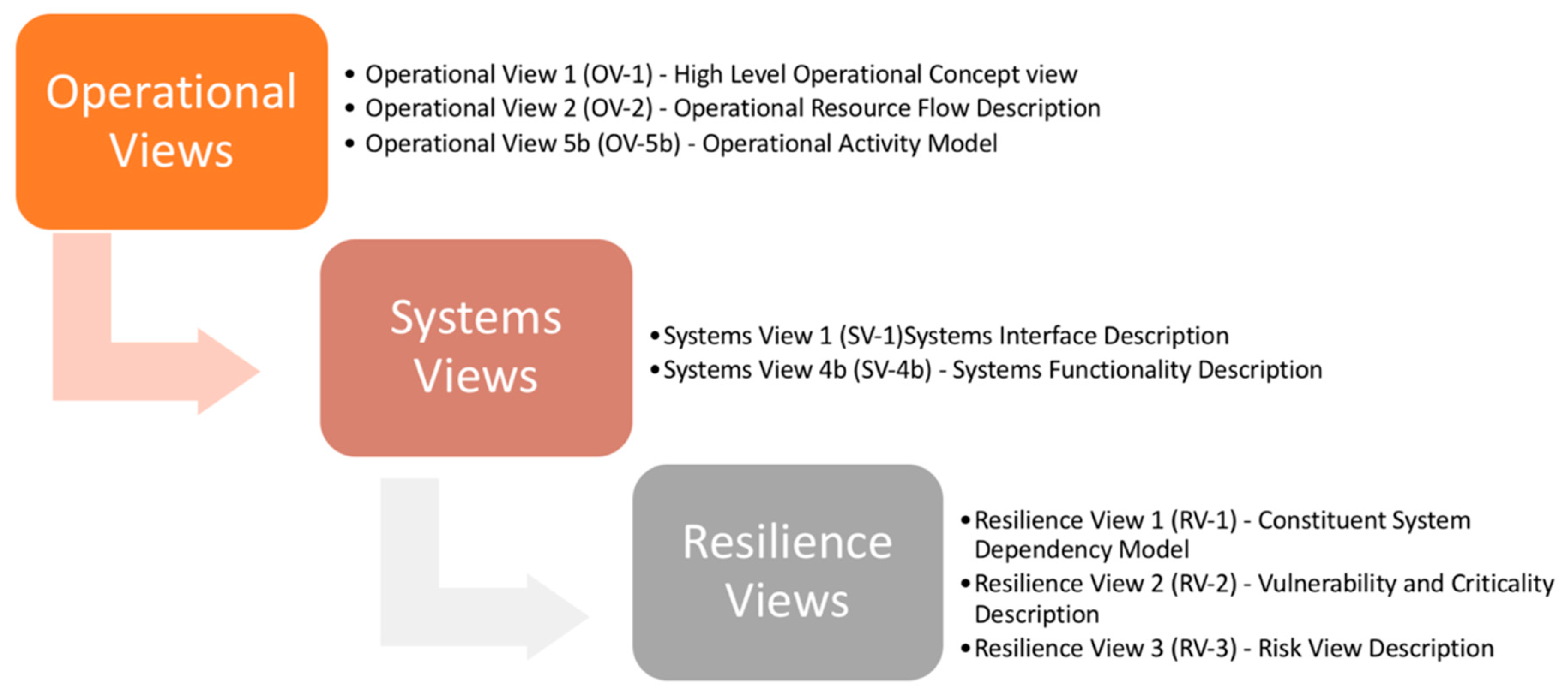
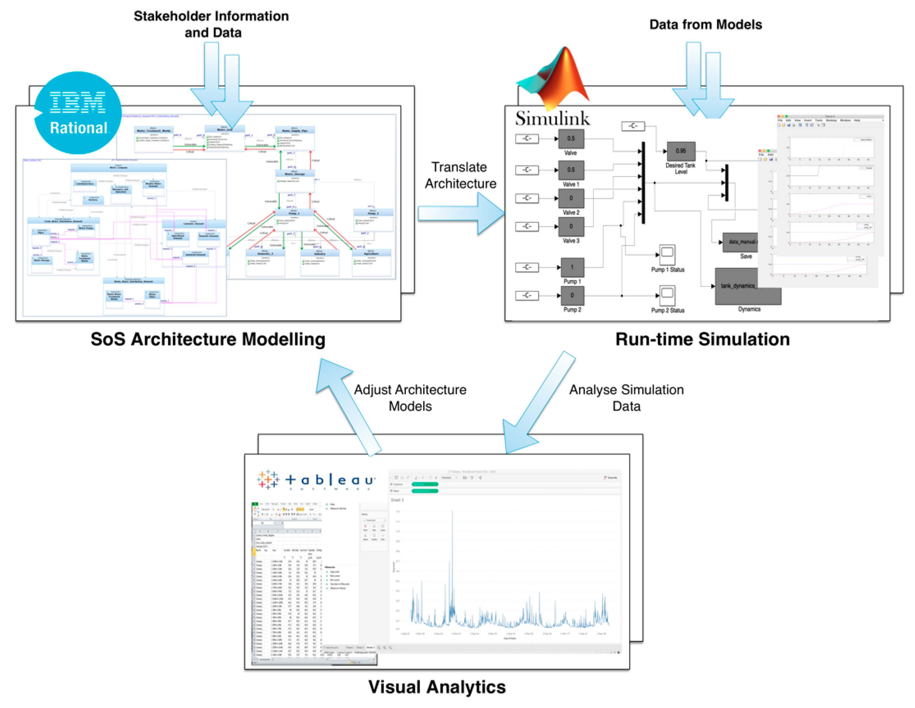
The SoS Resilience Framework/Methodology

The SoS resilience methodology is an encompassing set of methods and processes which helps decision makers, engineers and other stakeholders “design” resilience into SoS. The framework has been developed with the goal of evaluating resilience in the ‘as is’ state of the system and then implementing changes to target resilience in certain areas of the system which could be improved. The water scenario is a very useful case to test the methodology as it is representative of these types of mega-systems. Modelling and simulation (M&S) methods form the basis of the methodology, however it is a tool independent framework and can be replicated in a different set of modelling languages and tools, if required.
The methodology is systematic and takes a holistic approach to engineering future resilient systems. Stakeholder interaction is a fundamental characteristic of the methodology and subject matter experts (SMEs) from the water sector have been consulted throughout the application of the methodology at all phases. An overview of the developed framework is shown in Figure 3.
Phase 1. CONOPs and Resilience Requirements
Phase 1 commences with deriving a set of requirements specific to the area of concern and understanding the concept of operations (CONOPs) of the operational systems involved. The tools applied here are rich picture diagrams—a soft systems method [1]—and causal loop models [23,24] to understand the dynamic interactions between system elements. Subsequently a reference architecture [1,4,25] is created using systems modelling languages such as SysML and the Department of Defense Architecture Framework (DoDAF) [26] which is common language used to create systems architecture descriptions of systems and enterprises.
Phase 2. SoS Reference Architecture
The reference architecture forms the backbone to the methodology as it defines the interactions between constituent systems (CS) and sub-elements within the water SoS. A reference architecture, as the name suggests is a source of reference when regarding systems from different architectural perspectives. A set of views that form the reference architecture are shown in Figure 4. The architecture is a resource which is typically shared amongst project stakeholders, and engineering teams in the development phases of software, a product, a service, a system or an SoS. A common set of information is one of the key benefits of model-based systems engineering (MBSE) [27,28,29] and the purpose of a reference architecture, which is an MBSE practice.
Phase 3. Resilience Viewpoint
A novel viewpoint within the framework has been created solely focused on the resilience aspects of the architecture, and proposes three model types (Figure 4) to address; static structural analysis of the nodes within a network of systems and to explore the cascading effects of a failure or disruption; risks and those who are responsible for mitigating against risks, and; resilience attributes which are being designed into the architecture, for example, non-functional features referred to as “ilities” [30,31] such as flexibility, robustness, security, and availability. These non-functional properties are assessed through observation from the subsequent simulation models created in the next phases of the methodology.
Phase 4. Model-Integration Reference Architecture
The model-integration architecture provides the “big picture” view of the model architecture and puts it in context with the rest of the stakeholder’s model portfolio, showing how the project’s models and model platforms fit together. The importance of a modelling and the simulation integration framework cannot be overlooked, as it provides details at both high and low levels of granularity, conditional of the MBSE approach employed. This architecture specifies the tools used to develop models, data types, and the exchange of models and data between platforms and engineering teams. This process is highly recommended for when translating architecture to an executable model as it defines exactly what data is required for setting the parameters in the model. The integration framework is independent from the simulation tool; therefore, the engineer can select tools which are apt at a later date from when the architecture was created. The integration framework is beneficial in communicating requirements between stakeholders, and the “chief architect” and has the responsibility of gathering the essential information from individual model owners to generate a complete picture of the integration framework.
Phase 5. SoS/CS Simulation
Determining the resilience of an architecture is not a trivial task. A predominant reason for this is the nature of the architecture. Architectural designs are essentially static representations of the SoS whereas the real SoS is a dynamic entity whose behaviour is created from the interactions of the constituent elements. For successful analysis of SoS resilience to be conducted the SoS framework must consist of dynamic simulations to explore emergent behaviours which may arise from alternative architectures. The SoS reference architecture strongly supports the depiction of the SoS and its constituent systems, but it is desirable to represent the models that can be simulated in suitable simulation environments. In this case, the platform Simulink (MATLAB_R2018b, MathWorks, Cambridge, UK) was used—in conjunction with IBM Rhapsody which was used to create the architecture in phases 2, 3 and 4—to run simulations of supply and demand scenarios within a particular region of the UK.
Phase 6. Resilience Architecture Selection
This process is illustrated by Figure 5, where IBM Rhapsody architectures are manually translated into Simulink for simulation, and subsequent analysis in an additional visual analytics tool, in this case Tableau software (Tableau Desktop 10.5, Seattle, WA, USA). Simulink was selected as it permits the use of sliders and other parameter controls as the simulation runs in real-time. This enables decision makers to explore different parameters and immediately visualize the outputs.
Although an overall SoS resilience metric is desirable, it gives little information of the resilience at the local, CS level (or lower) which could be problematic when resilience is required in a specific area of the SoS. Uncertainty and unknown parameters are likely to make the task of achieving overall SoS resilience extremely difficult for the architect, hence why targeting resilience at the CS level is probably more logical. Metrics associated to executable architectures provide insight to the performance of technical and social systems which assist in the design space exploration process for more resilience solutions.

3. Case Study Results

3.1. Case Study Overview

This case study considers a scenario where flooding has resulted in pump failure (directly from flood water or from power failure), where the pump is a constituent system that forms part of the SoS. If we consider this case and assume that the flood has created a redundancy problem as the pump supplies multiple demand points within a network, it becomes evident that this challenge is greater than a redundancy problem and we must consider alternative resilience strategies to overcome the difficulties. Let us consider demand centres which are supplied by a water source of some kind (e.g., primary service reservoir) and utilise a pump to feed water up against gravity, to a set of demand centres via a number of service reservoirs. Of the four demand centres as seen in Figure 6, it is assumed (for demonstration purposes) that two are for domestic use, one for industrial and one for agriculture.
As previously mentioned, the resilience is the capacity of the water supply system to meet demands during emergency situations like floods, and in this case during the failure of a pump in the network. As it can be seen from Figure 6, this would cease supply to all four service reservoirs, enabling supply to the demand points until those service reservoirs completely depleted. Multiple strategies can be implemented, and numerous architectural variants can be suggested to increase the resilience here, however before getting to these, the upcoming results section shows the application of certain phases of the SoS resilience methodology.

3.2. Case Study Results

Following the phases outlined previously in Figure 3, a great understanding of the water SoS is achieved through applying CONOPs methods such as rich picture diagrams (Figure 1 and Figure 6) and causal loop models (Figure 7). The advantages of causal loop diagrams are that it helps analyse complex systems and helps identify key dynamic variables for later simulations. Cause and effect diagrams are a crucial aspect of designing resilience systems, particularly for understanding the dynamics between key variables. The loops which are created show an overall effect on the system and this is one of the elements of a causal loop diagram as illustrated in Figure 7, where the overall effect is a decrease in water available due to damaged infrastructure in times of a flood event. Although this seems a basic construct, reducing to this level of complexity is beneficial in exploring potential solutions, and determining the types of data sets required for simulating later in the process. Thus, from the causal loop it can be determined that the solution that needs exploring is the flexibility of the current systems in place to search for strategies and also architectural solutions which regulate the availability of water and hence, the supply of water to those that require it.
The rich picture and causal loop models helped define the requirements for this case study, and eliciting requirements for resilience in this case was done in collaboration with a range of stakeholders via small workshops, including; water companies, water consultancies and academics interested in water applications.
A subset of architecture models has been provided here to illustrate the type of modelling, but the reality is there would be numerous instances of some models from different stakeholders’ standpoints to describe the CSs and to elicit further resilience requirements. The two models here show a general Operational Viewpoint (OV-5b) of the water processing procedure and a Systems Viewpoint (SV-1) of the water companies’ systems arrangement and connectivity (Figure 8 and Figure 9, respectively). Figure 8 shows a high-level process model of taking raw water and passing it through a series of stages such as initial water storage, water screening, filtering etc. prior to being supplied for water customers and consumption. Figure 9 shows four high level components of a water system; a water company, distribution network, customers and consumers and waste water distribution network. Again, these are then populated with further subsystems which must be present to make the systems functional. Multiple instances of each model type can be created to model specific system structures, but these are for demonstration purposes.
Evolutionary development of the SoS architecture should be addressed by iteratively updating the specific constituent systems with the overall SoS in mind. The reference architecture is only as good as the quality of the information it holds and therefore, it is crucial that quality information is captured in its views/models. These static architectural representations go a long way in the design phases, allowing effective communication with stakeholders who have an influence on shaping the CS and the requirements definition process for future phases of the SoS evolution.
Subsequently, modelling the system using the resilience viewpoint (more specifically, Resilience View 2—RV-2) allows the engineer to highlight which nodes are critically dependent on each other and also to show which nodes are vulnerable if failure was to occur at some point in the network. For instance, modelling the case study example, shown in Figure 6, the viewpoint shows the four demand points being critically dependent on the functioning of the pump, and vice versa, the demand points being vulnerable on the pump failing. Similarly, the water storage component, or the primary service reservoir becomes vulnerable if the pump is no longer working, because that clean water has a set period which it can be stored for before becoming unsafe to distribute. Figure 10 shows the capability of RV-2 to model further details of each SoS component, for instance, the main supply pipeline has certain attributes which can be assigned to that element. These may include important parameters such as flow rates, flow direction, capacity, and others which are important in later simulation phases.
How would this look on the resilience curve? Referring back to Figure 2, the outage of a pump in a single pump supply system could result in curve 2b (ii), the performance dropping off to zero until that pump was restored. Alternatively, an architectural solution to the problem could be to add a secondary pump (Figure 11), that could be turned on immediately after failure, and performance would again increase back to a lower level of performance, or back to ideal performance P0. On the other hand, a decrease in performance could be avoided altogether if the failure of Pump 1 was anticipated, and Pump 2 switched on prior to failure.
At first glance, this may seem like an obvious problem with some obvious solutions to increase the resilience of supplying water to the consumers. Resilience here is considered as a redundancy issue. However, resilience can be a set of operational strategies implemented during a time of disruption to solve the supply problem. For example, prioritizing which demand points are more critical, decision-makers can set constraints on where to supply water and for which certain periods of time. For instance, it may be acceptable to supply the two domestic areas from say 6.00 am to 10.00 am and then from 3.00 pm to 10.00 pm in attempt to cut back on water consumption and resultant water waste. Another solution would be to decrease the pressure of which water is supplied to these points which would decrease the overall volume of water available to be used. Furthermore, depending on what is prioritised, the system may gracefully degrade its capacity to supply the two domestic points and the industrial point, reducing its supply to agriculture completely for a given period of time. This is one resilience strategy, although there will be many like this which should be explored architecturally and simulated to evaluate the feasibility of each one. These are just a few of many strategies which could be implemented to resolve the problem and, in the short-term at least, solve some issues of increasing resilience against flood scenarios.
From a risk perspective, the resilience viewpoint offers a model (Resilience View 3, RV-3) to capture risks which can be communicated with all stakeholder groups. Additionally, the risk view as illustrated in Figure 12, permits the architect or engineer to allocate the risks to constituent systems or stakeholders within the water SoS. This allocation of risks establishes responsibility of each identified risk and provides accountability to whom or to what is responsible for mitigating against that risk. The advantage from an architectural perspective is that risks can be avoided if mitigation strategies are embedded within the design of constituent systems. An example of an RV-3—Risk View Description—is shown in Figure 12. The example shows the risk of failure (or partial failure) of the water pump from the above example. Although this a simple example for demonstration purposes, the number of risks in a scenario like this are likely to be in the tens or hundreds, and this is a valued way to manage these risks as the complexity can be captured in multiple instances. This view (RV-3) within the resilience view package is a novel inclusion to the architecture framework which historically does not consider risks (in this way) as part of the architecture modelling phases of systems lifecycle modelling or development.
The final phase to be applied is simulation of architectures. Due to the nature of an SoS such as the water SoS, it is extremely important to simulate as much of the SoS and with as many of the CSs included as possible. The purpose of simulation in our case is to determine whether the overall resilience goals of the SoS can be satisfied by evaluating the interactions between the constituent systems and to understand where the current system falls short in terms of resilience. Since we cannot always rely on the CSs being modelled with the same tools, special techniques must be used to transform the architecture into a set of system models that can be executed within the same co-simulation [32] environment. Whilst it seems convenient for all CSs to be modelled using the same tool this is not always possible, nor desirable, due to commercial restrictions i.e., different water companies use different modelling tools and languages to design future capabilities. Also, it is highly probable that certain existing CSs have already been created and tested using other tools and provision should be made to use these wherever possible.
System dynamics (SD) [33] is an approach applied to understand the behaviour of complex, dynamic, nonlinear systems. Defining variables is a key step in creating an SD model, as these are assigned to specific model elements to simulate how changes in the system occur over time, and thus provide understanding of the basic structure of a system and the rationale for its behaviours. A positive of employing such a method in the SoS context comes from the need to understand the behaviour of the whole through understanding the behaviour of the interconnected parts. Numerical values can be assigned to the model and the dynamics can be simulated through execution of the variables. This study used the software tool, Simulink to create the model and simulation for our case study that stemmed from the specifications defined within IBM Rhapsody.
The Simulink model as seen in Figure 13 shows the element that reflects the problem scenario outlined in Figure 6, which looks at the use of pumps and valves to carry water from a primary reservoir, against gravity, to four service reservoirs which supply different types of customers (domestic, industry and agricultural). The model enables the user to set desired tank levels and the prescribed levels and to then manipulate the pumps and valves to direct water to specific service reservoirs depending on the resilience strategy in place. This specific strategy focussed on keeping the supply high to the two domestic customer groups i.e., service reservoirs 1 and 2, and to drop the amount of water being supplied to agriculture for the short term in order to maintain water to the domestic and industry customers. Preliminary results for this simulation run can be seen in Figure 14 where the domestic customers and their respective service reservoirs remain constantly at a high water capacity and the agricultural service reservoir (service reservoir 4) remains low. Service reservoir 3, the industry service reservoir fluctuates depending on the demand.
In order to test the model further, real data from the demand of customer groups and the volume and capacity of real reservoirs from specific locations will enable more accurate simulations to be run that are reflective of incidents in times of flooding. A great advantage of running a model like this is Simulink, in that it enables the engineer or decision maker to manipulate the parameters and variables using sliders and other input types to assess the response of the system in real time. Thus, allowing trade offs to be made in real time with respect to the events of a flood and the resilience strategies which are being tested and implemented.

4. Discussion

The methodology presented provides a means to explore resilience in SoS and to engineer resilience into systems such as the water SoS at multiple points within its lifecycle. Engineering resilience is a systematic endeavour and the model-based engineering methodology shown enables resilience to be evaluated in the ‘as is’ state and to explore future states to proactively mitigate against certain risks within particular contexts. Overall, the methodology will stipulate many outputs which are regarded as tools for engineering resilience in SoS. Such artefacts include; information about the water SoS which is stored within a reference architecture; architectural designs which can be stored as architecture patterns [34] for later re-use in design activities; simulation data which reflects the performance of architectures and helps inform decisions about architecture design; and finally; a detailed and shared understanding of key resilience challenges and issues, within the water sector, across a broad range of stakeholders.
In order to avoid commercially sensitive data, generic data was presented in this paper that is based on real water data to test the methodology. A significant result is the creation of a resilience viewpoint within an architecture framework that solely focusses on resilience. The anticipated future results would be to simulate some of the water architectures suggested to see how they perform using a resilience curve and to assess the responsiveness of certain designs. This would be done using the workflow as suggested in Figure 5, and data would be analysed to infer resilience measures for future SoS evolutions.
The intrinsic characteristic of any SoS is its state of constant flux and evolution. This means the reference architecture and subsequent simulations must be updated on a regular basis, especially when simulation results depart from the observed operation of the SoS. Attempting to perform this evaluation on the actual SoS is fraught with danger, because surprise emergent behaviours may be highly detrimental or unsafe. The reference architecture (blueprint) becomes an essential asset when considering the evolution of an SoS or where the SoS begins to exhibit unpredicted behaviour. However, we must always guard against the differences between the real world and the simulated SoS. Nevertheless, having a reference benchmark is extremely important. Similarly, maintaining a library of patterns for the constituent systems is very helpful not only in representing complex characteristics of the constituent systems but also in their reuse.
It was clear from the engagement with water companies and consulting companies that asset resilience is of high priority to water companies, in ensuring an aging infrastructure can meet the demands of present and future trends. To solve the challenges of modernizing infrastructure and maintaining waste water networks, there is an evident need for an interdisciplinary approach involving experts from water supply companies, systems engineers, climate experts, and key customers (domestic, industry and agriculture). By treating the water sector as an SoS, it should be possible to begin to address the more challenging aspects of ensuring resilience in water supply for the future; for example, the application of a reference architecture for mapping the current resources, surveying the current condition, analysing the problem areas, and understanding the nexus within all the stakeholders like geographical and economic implications. Strengthening the links between several elements from academic research and industry could make an important contribution to solving these challenges via the application of an SoS reference architecture.
Future work would include generating architectures that can be assessed quantifiably allowing resilience metrics to be developed for different types of SoS while measuring the performance of architectures can iteratively be done in modelling and simulation environments bespoke to these kinds of investigations. To also link the resilience curve with specific data from water supply failures would provide a way forward for quantifying resilience using some important metrics.
Where a pre-existing model of a constituent system exists, it is not always possible to guarantee that it will be compatible with the simulation environment. Therefore, care must be taken to understand the limitations of the model and its context of use. Such requirements place specific demands on the co-simulation environment, which must be a component-based simulator where system models are incorporated as the composition of a set of hierarchical modules. Consequently, the reference architecture must be structured to support a composition of constituent system models. Whilst this task is straightforward at the reference architectural modelling level, this requirement restricts the choice of simulation environment and depends on what simulations are needed. However, underlying this is a complex process of transforming system architectures into executable models [32], and something which should be looked into in future work.

5. Conclusions

This paper presents a methodology to explore resilience in the water sector from multiple perspectives, by adopting an SoS approach to problem solving. Water supply to flooding has been considered from an SoS standpoint, and the creation of a methodology allows resilience to be explored in many water scenarios to assess resilience and propose future designs. Resilience is seen as a new paradigm to risk management. A proactive approach is needed to explore future scenarios which may cause problems for systems with high dependencies and raise concerns with regards to system performance. Resilience engineering is seen as an important topic in the domain of systems engineering and certainly in sectors such as water, where the importance of successful operations is critical to human life and the environment.
Model-based systems engineering, and a structured framework or methodology allows decision makers and engineers to; (i) evaluate the resilience of current systems through static and dynamic methods, and; (ii) to discover future system states and resilience strategies through architecture exploration and implement them through a tested methodology. The water supply and flooding example shown within this paper illustrates the practicality of applying a set of MBSE methods to increase the resilience of systems which deliver water to consumers and demands points within a supply network. Water systems may suffer impairments and disruptions during times of severe weather, e.g., floods and droughts, or even failure due to legacy systems aging and failing naturally. The paper has shown how water may still be made available during a flood scenario, through architectural alternatives to deliver water prior and during a disruption. However, there are multiple variations of strategies and architectural alternatives which could provide a solution to this specific issue. Furthermore, water availability data of a specific region would help validate this process via informed simulation models, developed in conjunction with subject matter experts from a water company, however the methodology is a strong step in the right direction to explore resilience in SoS and the water sector during times of flooding.

Author Contributions

Conceptualization, D.J., R.K.; Data curation, D.J. and S.S.; Formal analysis, D.J. and S.S.; Funding acquisition, D.J. and R.K.; Investigation, D.J.; Methodology, D.J.; Project administration, D.J., R.K., M.R.C. and G.F.; Resources, D.J.; Software, D.J. and S.S.; Supervision, R.K.; Visualization, D.J.; Writing—original draft, D.J. and S.S.; Writing—review & editing, D.J., R.K., G.F., M.R.C. and F.M.

Funding

The authors would like to thank the EPSRC for the funding on BRIM (EP/N010329/1).

Conflicts of Interest

The authors declare no conflict of interest.

References

  1. Monk, A.; Howard, S. Methods & tools: The rich picture: A tool for reasoning about work context. Interactions 1998, 5, 21–30. [Google Scholar]
  2. Jenkins, G.J.; Murphy, J.M.; Sexton, D.M.H.; Lowe, J.A.; Jones, P.; Kilsby, C.G. UK Climate Projections: Briefing Report; Met Office Hadley Centre: Exeter, UK, June 2009; ISBN 9781906360023.
  3. HM Government UK Climate Change Risk Assessment; HM Government: London, UK, 2017; p. 24.
  4. Alessandra Scotto di Santolo UK Weather Warning: Expert Warns UK Heatwave is First of Many as Summers Will Get HOTTER. EXPRESS. 2018. Available online: https://www.express.co.uk/news/weather/997034/UK-weather-warning-climate-change-summer-heatwave-latest (accessed on 15 August 2018).
  5. Office for National Statistics. Overview of the UK Population; Overv. UK Popul.; Office for National Statistics: Newport, UK, July 2017; pp. 1–17.
  6. Hosseini, S.; Barker, K.; Ramirez-Marquez, J.E. A review of definitions and measures of system resilience. Reliab. Eng. Syst. Saf. 2016, 145, 47–61. [Google Scholar] [CrossRef]
  7. Tran, H.T.; Balchanos, M.; Domerçant, J.C.; Mavris, D.N. A framework for the quantitative assessment of performance-based system resilience. Reliab. Eng. Syst. Saf. 2017, 158, 73–84. [Google Scholar] [CrossRef]
  8. Bhamra, R.; Dani, S.; Burnard, K. Resilience: The concept, a literature review and future directions. Int. J. Prod. Res. 2011, 49, 5375–5393. [Google Scholar] [CrossRef]
  9. Woods, D. Four Concepts for resilience and the Implications for the Future of Resilience Engineering. Reliab. Eng. Syst. Saf. 2015, 141, 5–9. [Google Scholar] [CrossRef]
  10. Righi, A.W.; Saurin, T.A.; Wachs, P. A systematic literature review of resilience engineering: Research areas and a research agenda proposal. Reliab. Eng. Syst. Saf. 2015, 141, 142–152. [Google Scholar] [CrossRef]
  11. Adjetey-Bahun, K.; Birregah, B.; Châtelet, E.; Planchet, J.L. A model to quantify the resilience of mass railway transportation systems. Reliab. Eng. Syst. Saf. 2016, 153, 1–14. [Google Scholar] [CrossRef]
  12. Bergström, J.; Van Winsen, R.; Henriqson, E. On the rationale of resilience in the domain of safety: A literature review. Reliab. Eng. Syst. Saf. 2015, 141, 131–141. [Google Scholar] [CrossRef] [Green Version]
  13. Patriarca, R.; Falegnami, A.; Costantino, F.; Bilotta, F. Resilience engineering for socio-technical risk analysis: Application in neuro-surgery. Reliab. Eng. Syst. Saf. 2018, 180, 321–335. [Google Scholar] [CrossRef]
  14. Nelson, D.R.; Adger, W.N.; Brown, K. Adaptation to Environmental Change: Contributions of a Resilience Framework. Annu. Rev. Environ. Resour. 2007, 32, 395–419. [Google Scholar] [CrossRef]
  15. Hollnagel, E.; Paries, J.; Woods, D.D.; Wreathall, J. Resilience Engineering in Practice: A Guidebook; Ashgate Publishing Limited: Farnham, UK, 2011; ISBN 978-1-4094-1035-5. [Google Scholar]
  16. Haimes, Y.Y. On the definition of resilience in systems. Risk Anal. 2009, 29, 498–501. [Google Scholar] [CrossRef] [PubMed]
  17. Nan, C.; Sansavini, G. A quantitative method for assessing resilience of interdependent infrastructures. Reliab. Eng. Syst. Saf. 2017, 157, 35–53. [Google Scholar] [CrossRef]
  18. Gama Dessavre, D.; Ramirez-Marquez, J.E.; Barker, K. Multidimensional approach to complex system resilience analysis. Reliab. Eng. Syst. Saf. 2016, 149, 34–43. [Google Scholar] [CrossRef]
  19. Jamshidi, M. Systems of Systems Engineering: Principles and Applications, 1st ed.; Jamshidi, M., Ed.; CRC Press: Boca Raton, FL, USA, 2008; ISBN 978-1-4200-6589-3. [Google Scholar]
  20. Jamshidi, M. System Of Systems Engineering: Innovations for the 21st Century; Jamshidi, M., Ed.; WILEY: Hoboken, NJ, USA, 2009; ISBN 978-0-470-19590. [Google Scholar]
  21. Maier, J.; Eckert, C.; Clarkson, P. Model Granularity and Related Concepts. In Proceedings of the International Design Conference—Design 2016, Cavtat, Croatia, 16–19 May 2016; pp. 1327–1336. [Google Scholar]
  22. Maier, M. Art of Systems Architecting, 3rd ed.; CRC Press: Boca Raton, FL, USA, 2000; ISBN 9780849304408. [Google Scholar]
  23. Inam, A.; Adamowski, J.; Halbe, J.; Prasher, S. Using causal loop diagrams for the initialization of stakeholder engagement in soil salinity management in agricultural watersheds in developing countries: A case study in the Rechna Doab watershed, Pakistan. J. Environ. Manag. 2015, 152, 251–267. [Google Scholar] [CrossRef] [PubMed]
  24. Binder, T.; Belyazid, S.; Haraldsson, H.V.; Svensson, M.G.; Kennedy, M.; Winch, G.W.; Langer, R.S.; Rowe, J.I.; Yanni, J.M. Developing System Dynamics Models from Causal Loop Diagrams. In Proceedings of the 22nd International Conference on Neural Information Processing Systems, Vancouver, BC, Canada, 7–10 December 2004. [Google Scholar]
  25. US Dept. of Defence/Office of the DoD CIO. Reference Architecture Description; US Department of Defense: Washington, DC, USA, 2010.
  26. Hause, M. The unified profile for DoDAF/MODAF (UPDM) enabling systems of systems on many levels. In Proceedings of the 2010 IEEE International Systems Conference, San Diego, CA, USA, 5–8 April 2010; pp. 426–431. [Google Scholar]
  27. Ibarra-zannatha, J.M.; Limón, R.C.; Hernandez, W.E.C.; Electronico, I.; Estefan, J.A.; Obaidat, M.S.; Boudriga, N.A.; van der Aalst, W.M.P.; Voorhoeve, M.; Page, E.H.; et al. Survey of Model-Based Systems Engineering (MBSE) Methodologies 2. Differentiating Methodologies from Processes, Methods, and Lifecycle Models. Environment 1994, 32, 397–438. [Google Scholar]
  28. Piaszczyk, C. Model Based Systems Engineering with Department of Defense Architectural Framework. Syst. Eng. 2011, 14, 305–326. [Google Scholar] [CrossRef]
  29. Kalawsky, R.S.; O’Brien, J.; Chong, S.; Wong, C.; Jia, H.; Pan, H.; Moore, P.R. Bridging the gaps in a model-based system engineering workflow by encompassing hardware-in-the-loop simulation. IEEE Syst. J. 2013, 7, 593–605. [Google Scholar] [CrossRef]
  30. Ricci, N.; Fitzgerald, M.E.; Ross, A.M.; Rhodes, D.H. Architecting systems of systems with ilities: An overview of the SAI method. Procedia Comput. Sci. 2014, 28, 322–331. [Google Scholar] [CrossRef]
  31. Ross, A.M.; Rhodes, D.H. Towards a prescriptive semantic basis for change-type ilities. Procedia Comput. Sci. 2015, 44, 443–453. [Google Scholar] [CrossRef]
  32. Blochwitz, T.; Otter, M.; Arnold, M.; Bausch, C.; Clauß, C.; Elmqvist, H.; Junghanns, A.; Mauss, J.; Monteiro, M.; Neidhold, T.; et al. The Functional Mockup Interface for Tool independent Exchange of Simulation Models. In Proceedings of the 8th International Modelica Conference, Dresden, Germany, 20–22 March 2011; pp. 173–184. [Google Scholar]
  33. Salzano, E.; Di Nardo, M.; Gallo, M.; Oropallo, E.; Santillo, L.C. The application of System Dynamics to industrial plants in the perspective of Process Resilience Engineering. Chem. Eng. Trans. 2014, 36, 457–462. [Google Scholar]
  34. Kalawsky, R.S.R.S.; Joannou, D.; Tian, Y.; Fayoumi, A. Using Architecture Patterns to Architect and Analyze Systems of Systems. Procedia Comput. Sci. 2013, 16, 283–292. [Google Scholar] [CrossRef] [Green Version]
Figure 1. Rich picture of UK water sector.
Water 11 00496 g001
Figure 2. (a) Generic resilience curve; (b) different impacts on resilience.
Water 11 00496 g002
Figure 3. System-of-systems (SoS) resilience methodology.
Water 11 00496 g003
Figure 4. Architecture modelling views process.
Water 11 00496 g004
Figure 5. Modelling and simulation workflow.
Water 11 00496 g005
Figure 6. Case study scenario.
Water 11 00496 g006
Figure 7. Causal loop of water problem.
Water 11 00496 g007
Figure 8. OV-5b—Operational view of high-level water treatment process.
Water 11 00496 g008
Figure 9. SV-1 Water Company systems.
Water 11 00496 g009
Figure 10. Resilience View 2 (RV-2) pump failure.
Water 11 00496 g010
Figure 11. RV-2—Two pump architecture solution.
Water 11 00496 g011
Figure 12. Resilience View 3 (RV-3)—Risk view description.
Water 11 00496 g012
Figure 13. Simulink model.
Water 11 00496 g013
Figure 14. Service reservoir capacity from simulation run.
Water 11 00496 g014

