Design Parameters of Hot-Water Drilling Systems
by
Gang Liu
1,2,3, 
Pavel Talalay
1,3,*,
Rusheng Wang
1,3,
Yang Yang
1,3,
Jialin Hong
1,3,
Da Gong
1,3,
An Liu
1,3 and
Dayou Fan
1,3 1
Polar Research Center, Jilin University, Changchun 130026, China
2
Architectural College, East China Institute of Technology, Nanchang 330013, China
3
College of Construction Engineering, Jilin University, Changchun 130026, China
*
Author to whom correspondence should be addressed.
Water 2019, 11(2), 289; https://doi.org/10.3390/w11020289
Submission received: 7 December 2018
/
Revised: 29 January 2019
/
Accepted: 1 February 2019
/
Published: 7 February 2019
(This article belongs to the Section Water Resources Management, Policy and Governance)
Abstract
:Currently, hot-water drill systems are actively used to observe ocean cavities under ice shelves, detect the effects of climate change on glaciers, retrieve sub-ice seabed samples, study the internal ice structure with video imaging, log temperatures, measure deformations within ice, determine basal sliding velocity, provide clean access to subglacial lakes, and many other scientific applications. The main parameters of hot-water drilling systems in any configuration are flow rate, delivery pressure, and temperature of the delivered water. The controlled outcome variables are the diameter of the drilled borehole, rate of penetration, power and fuel consumption for ice melting, and refreezing rate of the borehole. The independent variables while drilling are the current/target depth and the temperature of the ice. The paper aims to present a design procedure for hot-water drilling parameters that are necessary to choose appropriate equipment and tools at the planning stage.
1. Introduction
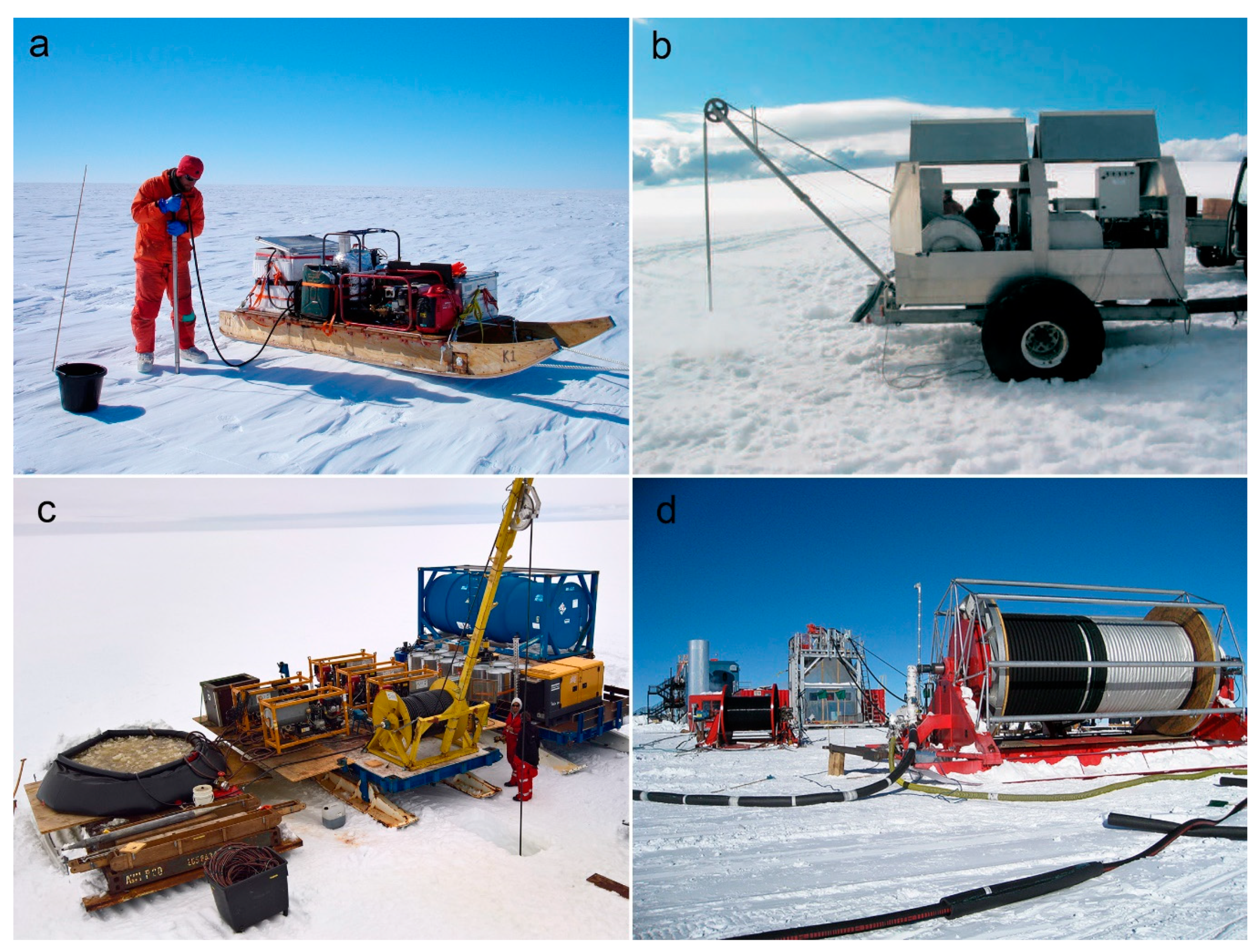
In the 1970s, hot-water ice drilling technology was introduced by French and Swiss scientists as one of the fastest methods to drill boreholes in glaciers [1,2]. Nowadays, hot-water drill systems are actively used for different tasks that can be subdivided by depth as shown (Figure 1): (1) near-surface drilling up to 50–60 m for ablation stakes installation, temperature measurements, access to lake/ocean water, and seismic surveying [3,4]; (2) shallow drilling up to 300–400 m for monitoring glacier dynamics, basal sliding, and englacial water pressure [5,6]; (3) intermediate drilling up to 1500 m for studying marginal parts of the Antarctic and Greenland ice sheets, for access holes through ice shelves, and for subglacial lakes exploration [7,8,9]; and (4) deep drilling up to a depth of 3500 m for subglacial exploration, installation of neutrino detectors, and other scientific applications [10,11]. Even coring of ice is possible with hot-water drilling [12,13].
Numerous hot-water drills have been constructed by combining water pumps and heating units, with individual specifications matched to achieve certain drilling rates over anticipated ranges of borehole depths, borehole widths, and ice temperatures. However, the principle of all systems is the same: hot water is pumped and pressurized through the drill hose to a nozzle that jets hot water to melt the ice. In many cases, the drilling process consists of two phases: (1) drilling in the narrow sense, when the drill melts its way down through the ice, and (2) reaming, when the drill is raised or lowered with the hot water continuing to flow. The reaming enlarges the hole and keeps warm water in contact with the borehole for longer to give more heat an opportunity to conduct into the ice, but this will not be a concern in the paper. By warming the ice surrounding the hole, it takes longer for the borehole to close. This is critical, as there must be adequate time after producing the hole to insert and lower the instrumentation before the borehole becomes too small.
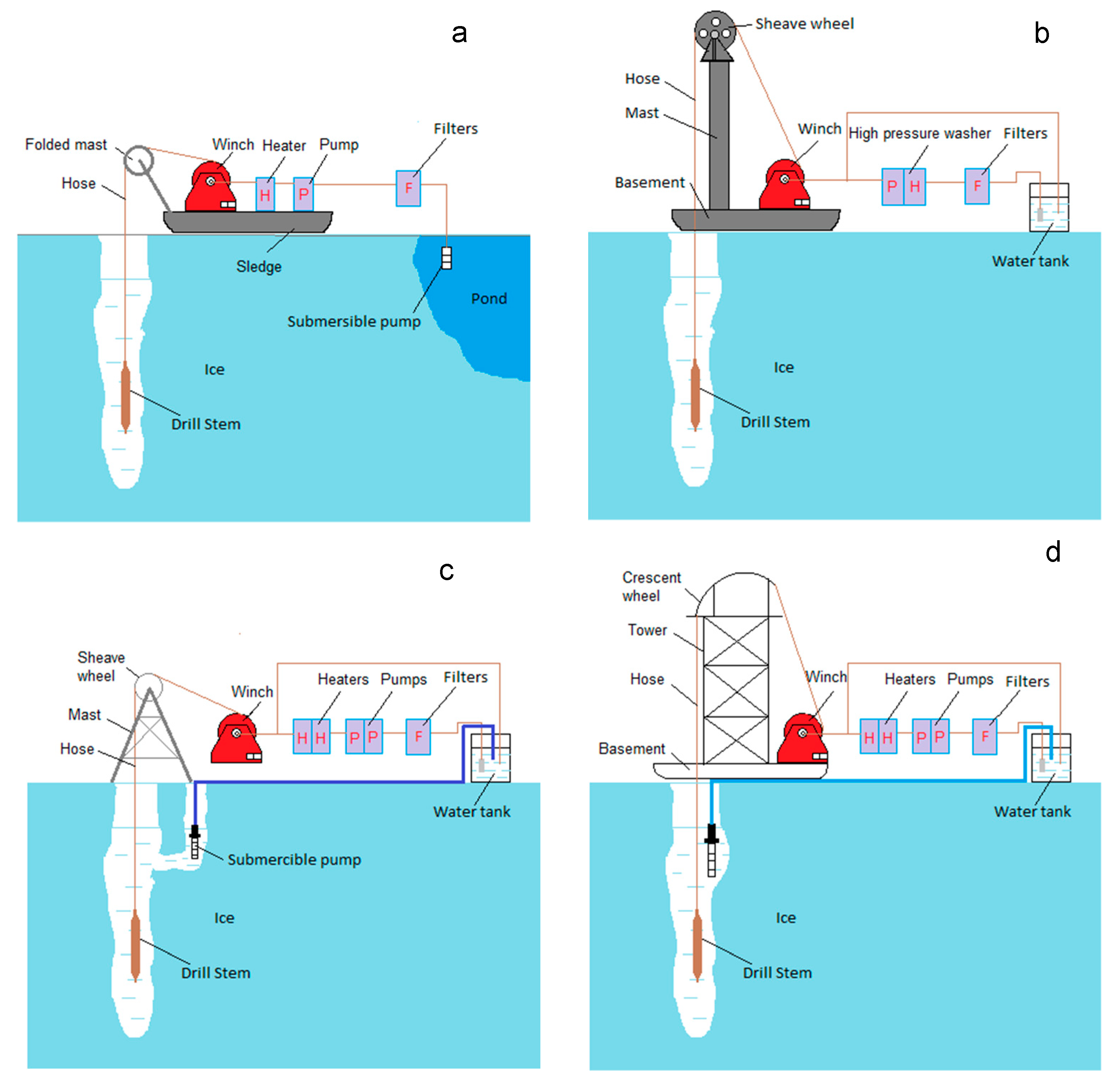
Water serves as a heat transfer conduit and drilling fluid at the same time. Several approaches to obtain water for drilling are used (Figure 2): (1) surface runoff water from mountain glaciers and the Greenland ice sheet that melts in the summer; (2) water melted in containers or tanks from surface snow and ice; (3) water from a supplementary borehole drilled nearby and connected with the main borehole by a subsurface cavity; and (4) water pumped out directly from the drilled borehole. The best practice is to use local surface meltwater if available or to recirculate water back from a drilled hole, because melting snow is difficult and doubles the fuel consumption. However, if the recirculating water is used, a meltwater tank is also necessary to start drilling, and to a far lesser extent to compensate for the density difference of the ice and water replacing it.
Depending on drilling targets, hot-water drills can produce small-diameter holes (up to 100–150 mm), intermediate-diameter holes (up to 300–350 mm), and large-diameter holes (up to 600–1000 mm). Small-diameter holes are typically produced when drilling shallow and intermediate-depth boreholes to depths of 500–800 m [5,6]. However, to deploy samplers and other instrumentation, the size of hot-water boreholes has to be increased to 250–350 mm [7,8]. There are some special cases when a melted borehole should be very large, e.g., the required hole diameter in the IceCube project was as large as 0.6 m to deploy the digital optical modules [10]. The WISSARD project also required large-diameter holes (1 m) for the deployment of large scientific payloads, such as the Sub-Ice Rover [9].
The main parameters of hot-water drilling systems, regardless of configuration, are flow rate, delivery pressure, and temperature of the delivered water. The controlled outcome variables are the diameter of the drilled borehole, rate of penetration, power and fuel consumption for ice melting, and refreezing rate of the borehole. The independent variables while drilling are the current/target depth and temperature of the ice. There are some other issues that should be also taken into consideration by engineers during the planning stage: the size and mass of the whole system and individual components; a list of measured/controlled parameters and a reliable control system; maintenance, assembly, and disassembly of the system; drill nozzle design; and methods for preventing freezing when transporting or otherwise shutting down a hot-water drill. However, a consideration of these issues is beyond the scope of this study.
There are several publications that include estimations of the borehole size, lifetime, and other parameters of hot-water drilling systems [14,15,16], but the design principle of the entire system is lacking. The focus of this paper is to present the design procedure of hot-water drilling parameters that are necessary to choose appropriate equipment and tools on the planning stage.
2. Main Parameters of Hot-Water Drilling System
2.1. Minimum Flow Rate of Hot Water
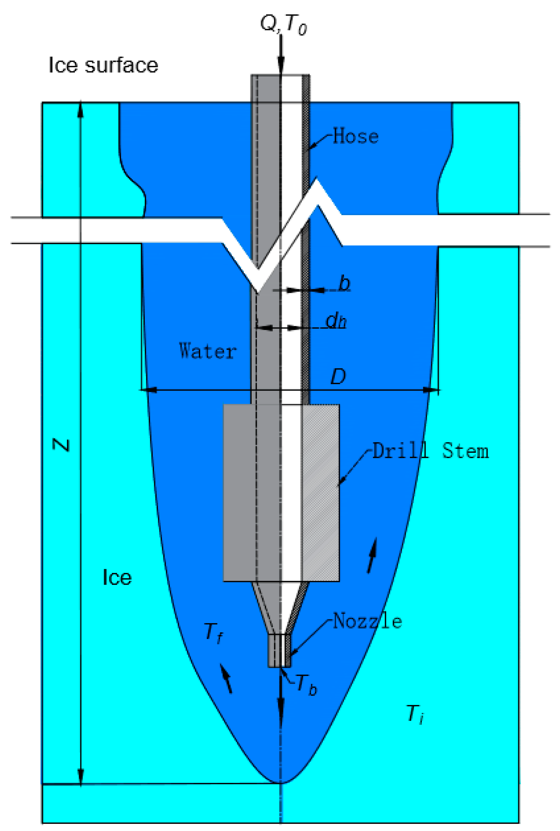
The heat from hot water spraying out of the nozzle (Figure 3) is used for (1) raising ice temperature to its melting point; (2) melting ice; and (3) mixing with melting water and raising the water temperature to a balance temperature. The energy balance at the bottom-hole area can be estimated as [5,15,17]:
where Q is the mass flow rate of hot water, kg s−1; Cw is the heat capacity of water, J kg−1 K−1; Tb is the bottom temperature of drilling water that sprays out of the nozzle; Tf is the final temperature of the mixture of hot water and melted ice, °C; ρw is the density of the drilling water, kg m−3; ρi is the density of the ice, kg m−3; D is the mean diameter of borehole, m; Δz is the depth increment, m; li is the latent heat of the melted ice, kJ kg−1; ε is the coefficient accounting for the lateral conductive heat losses in ice masses outside of the borehole (Zotikov suggested that this part of heat losses could be estimated as 2–5% of the energy to raise the initial ice temperature to the melting point [18]); Ti is the ice temperature, °C; Ci is the heat capacity of ice J kg−1 K−1; and t is time, s.
The drilling depth divided by the drilling time ∆z/t can be replaced by rate of penetration (ROP) v, and after rearrangement, we get the required flow rate:
If the heat input is fully used in melting ice (energy exchange efficiency is 100% at the bottom-hole area), then Tf = 0 and the minimum flow rate will be as follows:
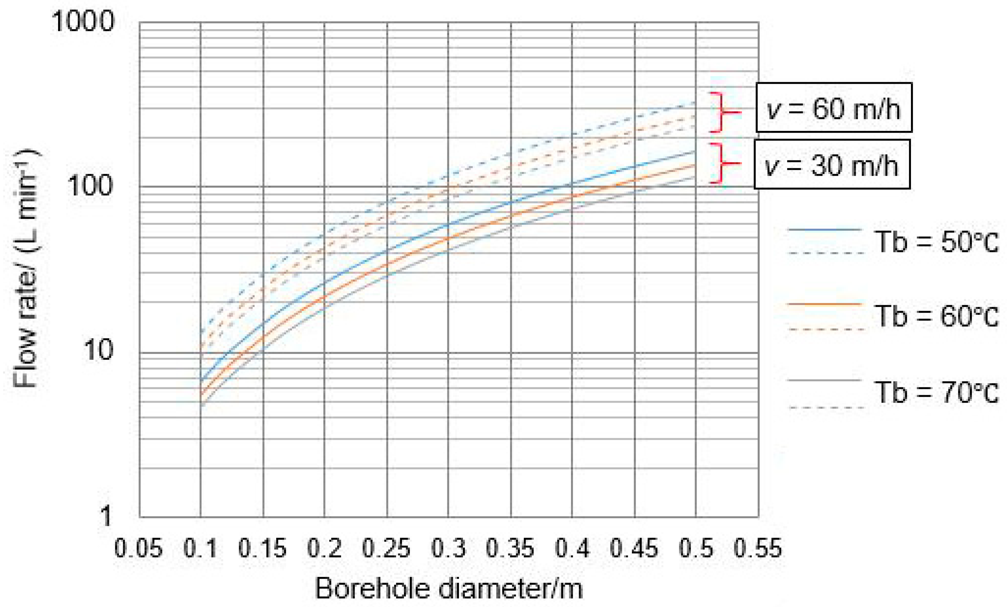
As the temperature of ice is an independent factor that cannot be changed, there are only three variables that influence the choice of flow rate: the desired ROP, required borehole diameter, and bottom temperature of the drilling water. For some special purposes such as deploying instrumentation into/through the ice, the borehole diameter should be not less than a specified value, while in the other cases, drilling should be as fast as possible.
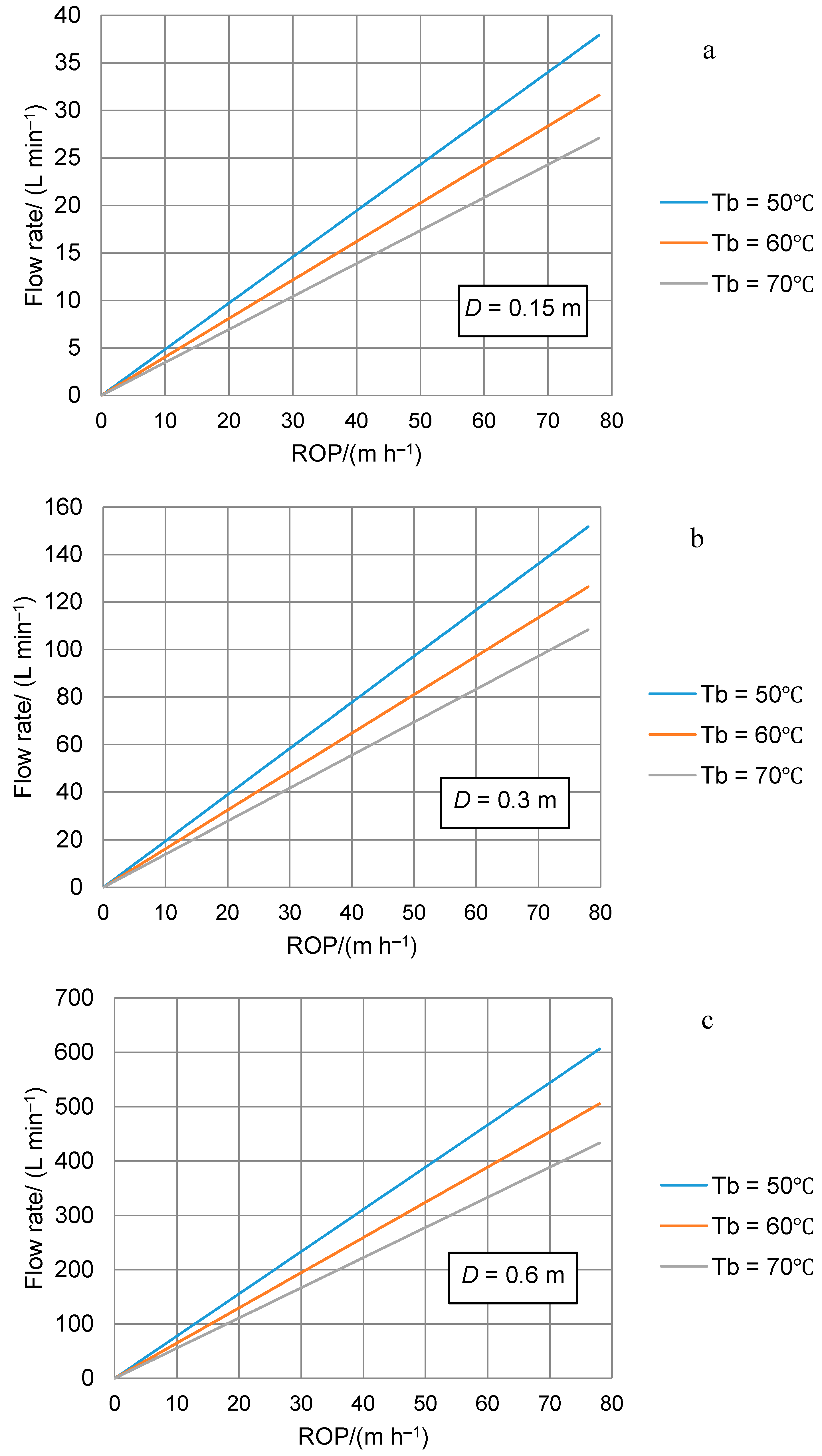
To drill holes with v = 30 m h−1 (that could be considered as the minimal desired ROP) and mean diameter ≥0.3 m, the minimum flow rate should be ≥60 L min−1, assuming that the temperature of the sprayed hot water at the bottom of the hole Tb ≥ 50 °C (Figure 4). The ROP is directly proportional to the flow rate of hot water (Figure 5). To drill as fast as possible, one needs to follow the simple rule: higher flow rate and higher temperature lead to a higher ROP. Both parameters are limited by the capacities of the commercially available or customized equipment planned to be used in the system. Considering that the borehole is usually not round and that the energy efficiency at the melting region cannot achieve 100%, we suggest to choose a rate 1.2–1.5 times higher than the minimum flow rate as the final choice.
2.2. Delivery Pressure
Because hot water flow moves down through the hose, losses due to friction between the moving liquid and the walls of the hose cause the pressure within the pipe to reduce with distance; this is known as head loss. In addition, changes in flow velocity due to changes in the geometry of a fluid system (i.e., changes in cross-section, bends, nozzle, and other fittings) set up eddies in the flow, resulting in energy losses. The delivery pressure pp (Pa) from the pump should not be less than the head losses in the hot-water circulation system, accounting for the kinetic energy of spray-out water [19]:
where ks is the safety coefficient (in conventional rock drilling, ordinarily ks = 1.3–1.5); Σpf are friction pressure losses, Pa; Σpl are local pressure losses, Pa; and U is the speed of water flow, m s−1.
Friction pressure losses depend on the length of the flow line, fluid characteristics (viscosity, density, Reynolds number), and hose roughness, and can be calculated using the well-known Darcy–Weisbach equation:
where λr is the roughness coefficient; L is the total length of the circulation line, m; and dh is the inner diameter of the hose, m.
The speed of flow can be easily calculated according to:
where Qw is the actual flow rate of the water, m3 s−1.
For laminar flow, the roughness coefficient λr is completely independent of roughness itself and varies only with the Reynolds number Re that is the relative strength of the viscous and inertial forces:
where ν is the kinematic viscosity of the drilling fluid, m2 s−1.
In the range of Reynolds numbers from 2000 to 4000, the flow changes from laminar to turbulent. Values of λr are uncertain in this range. If the circulation system was designed for flow in this range, the only safe procedure would be to assume that flow is turbulent. When flow occurs at Reynolds numbers greater than 4000, values of λr in the Darcy–Weisbach formula vary with roughness as well as with viscosity and density, and the friction factor is less clearly defined because radial components of velocity exist and there is an interchange of momentum between adjacent layers of fluid. Turbulent flow may be divided into three categories: flow in smooth hoses, flow in relatively rough hoses at high velocities, and flow in the transition zone between the first two categories. On all occasions, we observe the turbulent flow in hot-water drilling systems, and the surface roughness does not protrude beyond the laminar sublayer of the boundary flow. In general, we could solve Equations (6) and (7) to get a Reynolds Number and choose the proper roughness number. In our case, Re is within the range of 105 and 3 × 10⁶, and at turbulent flow, the roughness coefficient approaches closely to [20]:
Local pressure losses are usually expressed in terms of the local loss coefficient kl that depends on the geometry of circulation system:
For a long, uniform, straight hose, the local pressure losses are far less than the friction losses. Even if the exact geometry of the fluid loop is not known, in a first approximation, we consider less than 20 abrupt contractions and entrances, 20 sharp bends, 20 valves, and 20 exits and abrupt expansions. In this case, the total local pressure losses at the surface are lower than 0.05 MPa [21].
The highest local pressure losses are observed in the drill nozzle, with the diameter being far less than the hose diameter. The higher the water jet exit velocity, the higher the ROP can be if it is required. Typically, the pressure drop across the nozzle would be in the range of 0.5–1.0 MPa to give the exit velocity of 30–40 m s−1 that is essential for rapid hole formation in advance of the drill nozzle, thus maintaining both an acceptable ROP and hole verticality, and making the hole diameter large enough to allow the nozzle to pass through with further melting taking place over several meters above the nozzle [8].
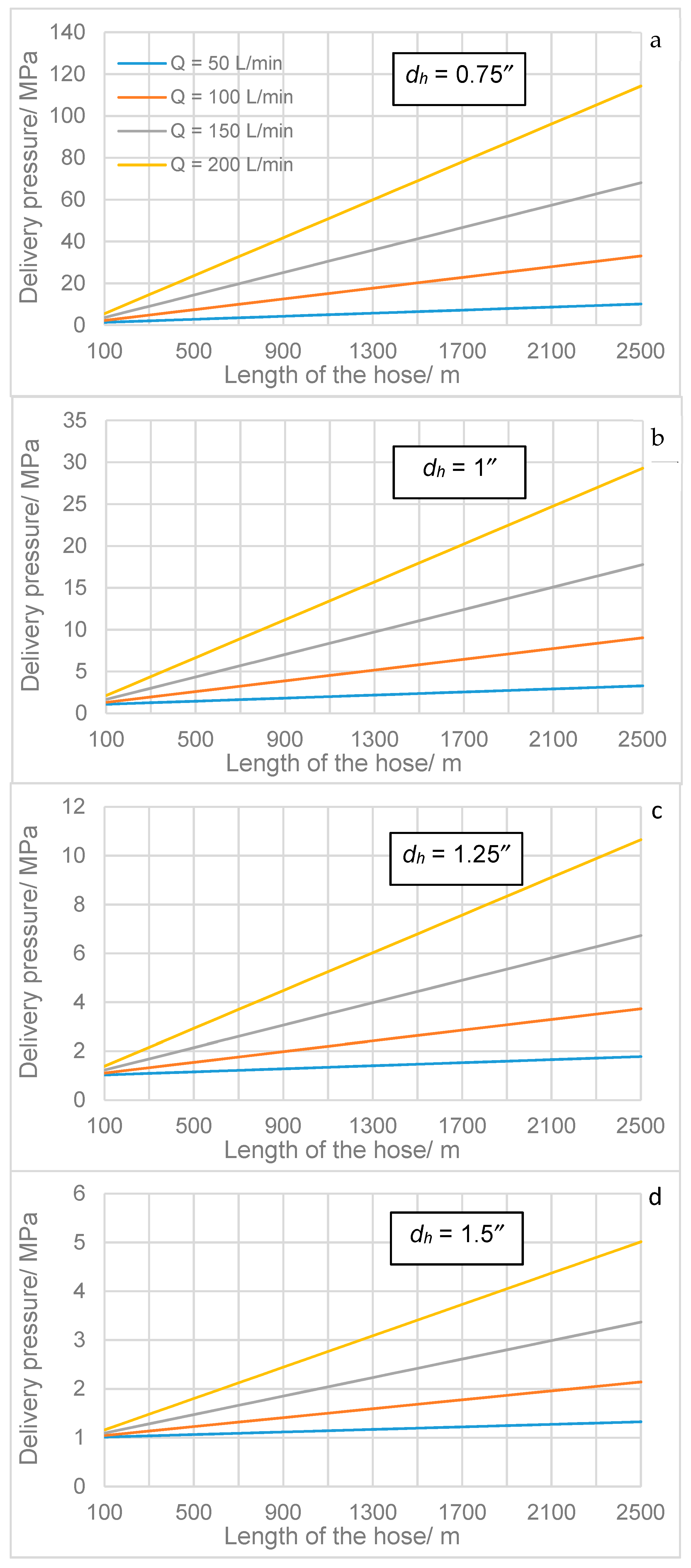
In most cases of intermediate or deep hot-water drilling, the friction pressure losses play the main roles in the required delivery pressure of the hot water flow, which mostly depends on the length of the hose, the hose diameter, and the flow rate (Figure 6), while the local pressure losses may be much more important for shallow drills to provide a strong contact upon bottom ice. 5 MPa is enough for a 200 L min−1 flow in a 2500 m and 1.5″ hose, while it can be 10 MPa for a 50 L min−1 flow in a 2500 m and 0.75″ hose. For a common 200 L min−1 hot-water project whose target depth is more than 1000 m, the hose diameter is preferably at least 1.25″.
2.3. Initial Temperature of Hot Water
When drilling water flows through the long-distance hose, the temperature rapidly decreases from the surface to the nozzle. Therefore, hot-water drills have a limitation in their depth range: the limit is reached when the hot water flowing through the drill-hose cools to the freezing point by the time it arrives at the drill-nozzle. Assuming a constant heat transfer coefficient along the hose length, Taylor suggested the following equation to estimate heat loss through the drill-hose wall [16]:
where k is the coefficient of thermal conductivity of the hose, J s−1 m−1 K−1; dh and b are the hose diameter and wall thickness, respectively, m; z is the borehole depth, m; and T0 is the initial temperature of water, °C.
Meanwhile, heat transfer theory gives the following equation for heat loss in the hot-water down flow [22]:
Equating the heat losses and rearranging gives the following equation for the initial temperature of the water:
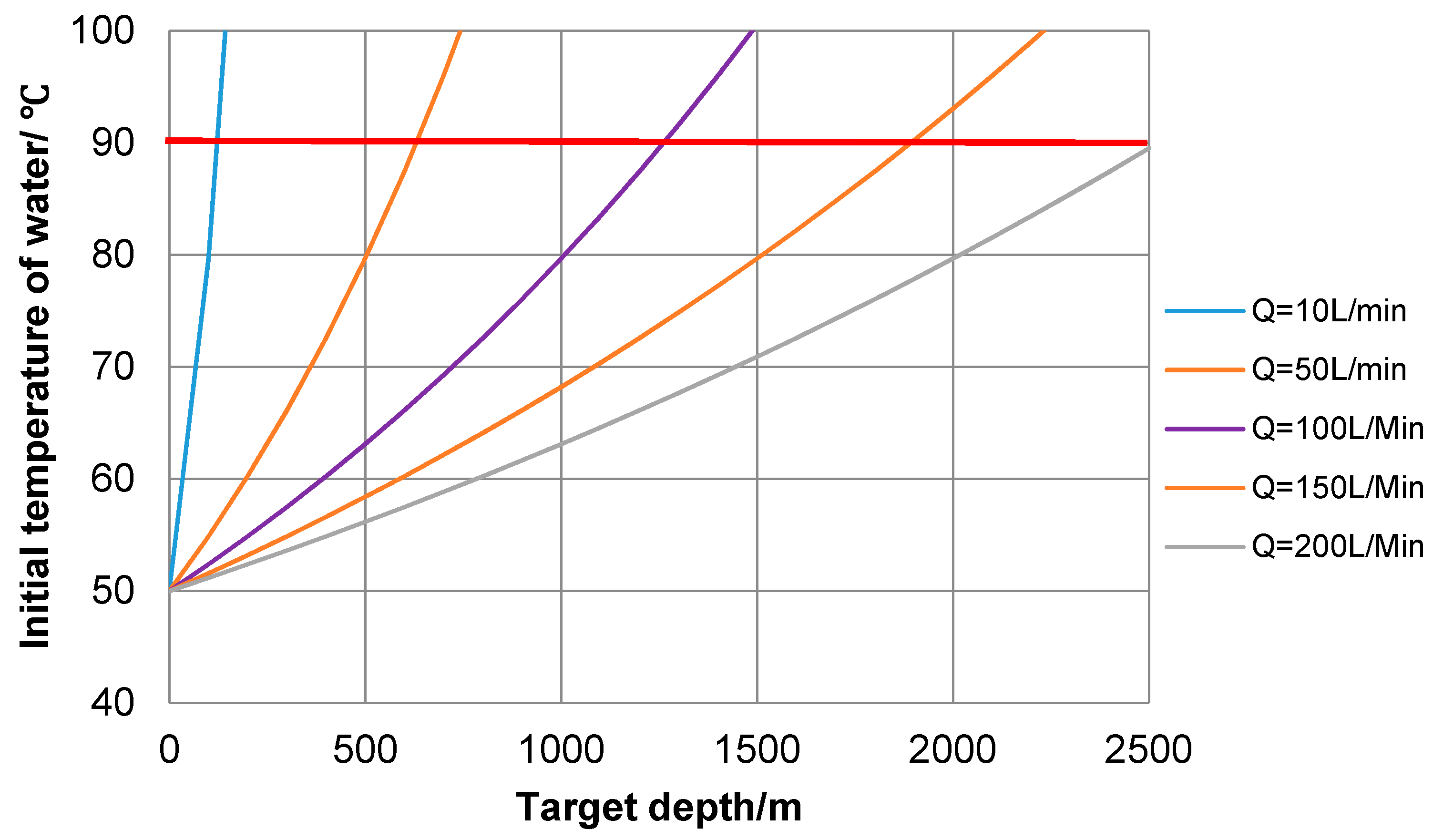
In the general case, the initial temperature of the water increases with Tb, k, dh, and z, and decreases with an increase in Cw, Q, and b. Figure 7 shows the required initial water temperature depending on target depth, assuming Tb = 50 °C, b = 11 mm, dh = 38 mm, k = 0.3 J s−1 m−1 K−1, and Cw = 4190 J kg−1 K−1. The hot water supply temperature can reach as high as 80 to 100 °C depending on the drill site elevation and boiler capacity. Assuming the maximal initial temperature of hot water as 90 °C, using pumps with a rated flow rate of 50 L min−1 has a target depth limitation of 600 m, 100 L min−1–1200 m, and 150 L min−1–1900 m. If the target depth is 2000 m, the initial temperature must be at least 80 °C at a 200 L min−1 flow rate.
As Cw is a constant and a thicker hose means a heavier hose and a bigger reel, a relatively high initial temperature and flow rate are desirable. With higher T0 and Q, drilling is faster, but the same fraction of heat is lost from the hose. A larger hose diameter may cause temperature loss, but it is beneficial because it can reduce hydraulic resistance. A deep borehole will dramatically decrease the temperature, so we come to the same conclusion: it is crucial to have a high initial temperature and a large flow rate.
3. Controlled Outcome Variables of Hot-Water Drilling
3.1. Average Diameter of Borehole and Rate of Penetration
According to Equations (1) and (13), when the flow rate and initial water temperature are decided, the mean diameter of borehole can be estimated through ROP as follows:
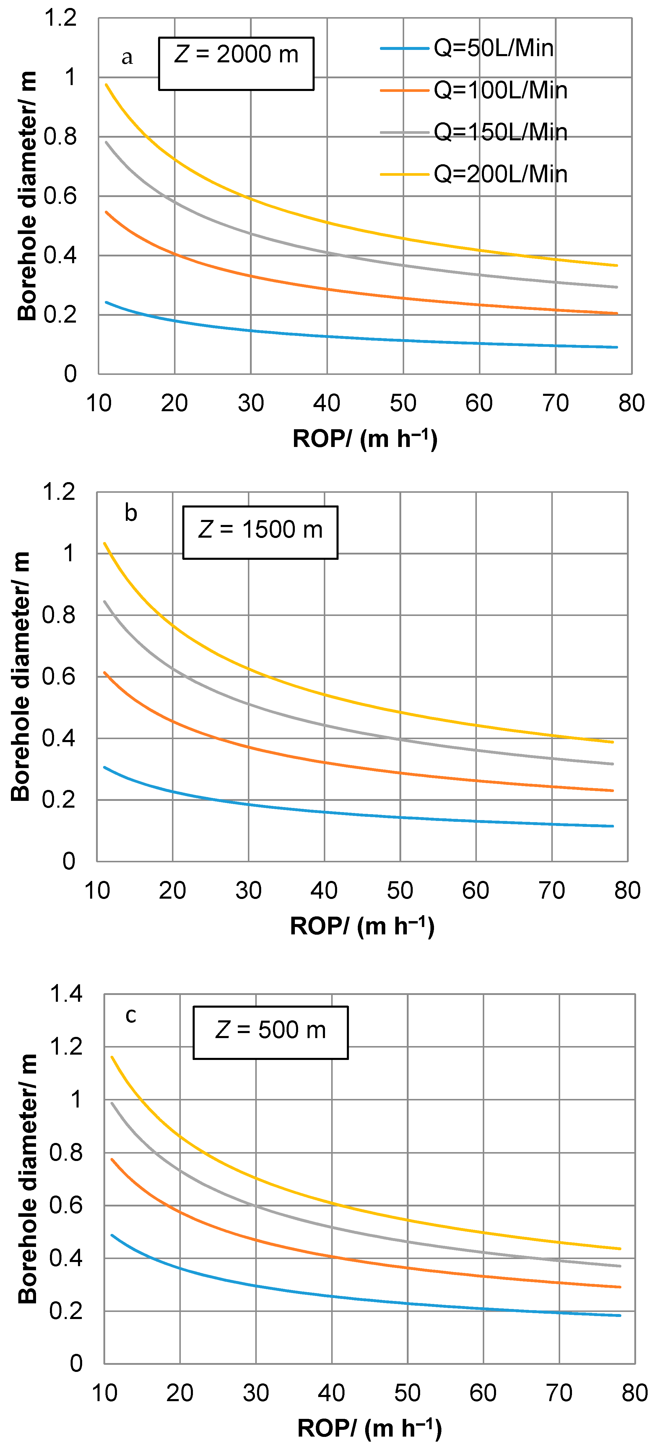
An increase in flow rate would directly proportionally increase the ROP and increase the borehole diameter by the square law. In most cases, the ROP is controlled by the operators to ensure that the tip of the drill nozzle is in a spaced position from the bottom of the hole. Figure 8 shows the borehole diameter changing with an initial temperature of water at 90 °C vs. the ROP (other parameters are the same as in the previous section). The penetration rate slows in deeper boreholes. A high flow rate and high bottom temperature both increase intensification of the drilling process. A drilling operator manually controls the proper ROP, obtaining the desirable diameter. To create a large diameter borehole, the penetration should be slow. This means that the control system including corresponding sensors is crucial to obtain the right diameter and high ROP, and the operators’ experience is also highly valuable.
3.2. Power and Fuel Consumption for Ice Melting
If we already know the initial temperature of delivering hot water, and with the assumption that all the water is heated from 0 °C to T0, the conservative estimates of fuel consumption for heating the water is [22]:
For example, to create a flow rate of 200 L min−1 of the hot water with a temperature of 90 °C, drillers need to spend 1257 kW of heating power. Such a huge power supply is usually powered by a diesel burner or boiler. If the efficiency of the diesel boiler is 90%, it would typically consume ~152 L h−1 of fuel for this case.
Combining Equations (1) and (13), with the assumption that , we can get:
We could also get the approximate fuel consumption for a planned hot-water drilling project (without considering fuel consumption for borehole reaming if it would be necessary):
where Cfuel is the fuel consumption, L per m of drilled borehole; and q is the calorific value of diesel, kJ L−1.
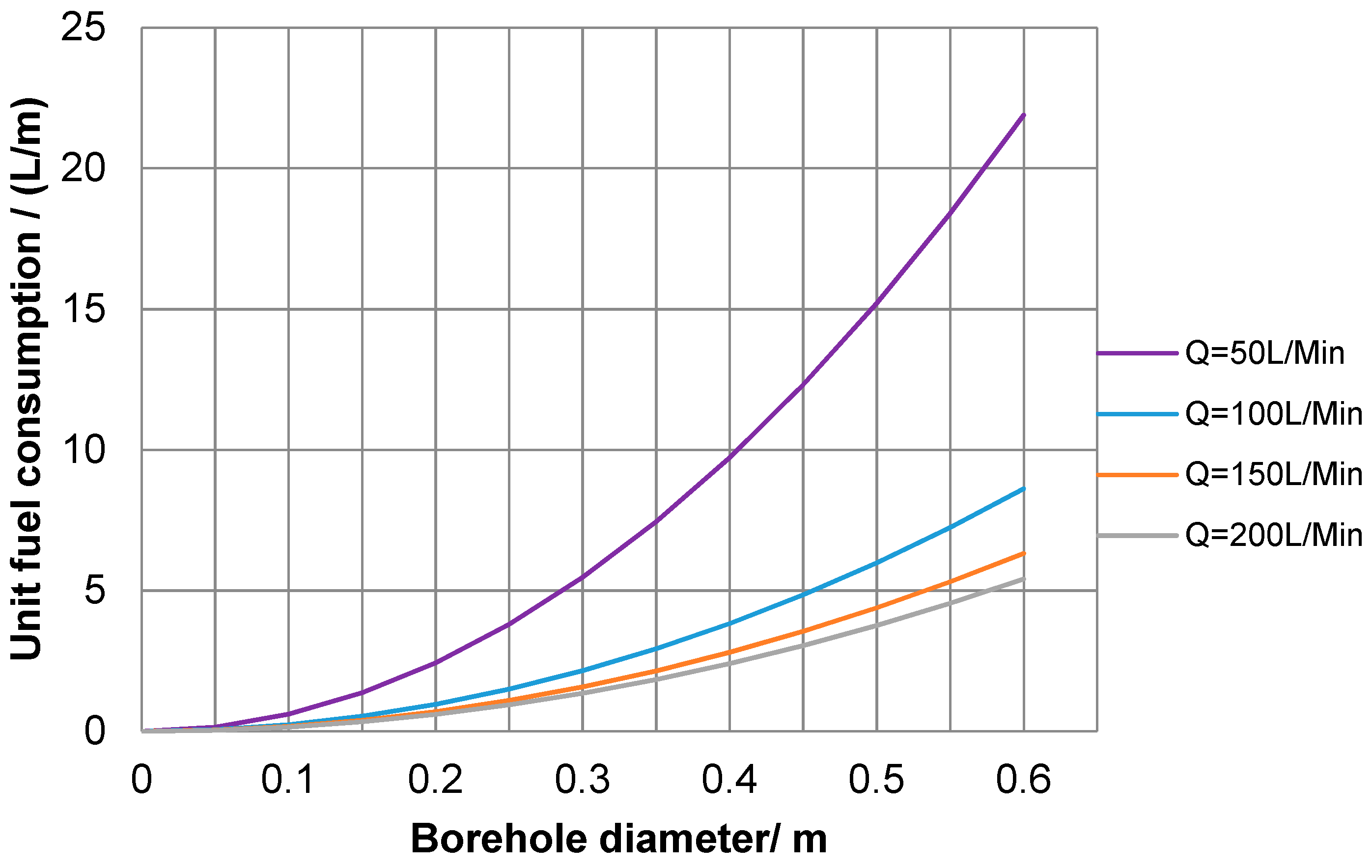
As the target depth is chosen, fuel consumption is only determined by the borehole diameter and hot water flow rate (Figure 9). It should be noted that a larger flow rate may decrease fuel consumption because of less heat loss in the hose. In fact, a larger flow rate would tremendously increase the ROP and decrease drilling time per hole, thus decreasing heat conduction into the surrounding ice and thereby saving fuel consumption. Essentially, the tradeoff between flow rate and fuel consumption comes down to time—the high flow rates require much greater rates of fuel consumption, but they result in much higher rates of penetration; it takes much longer to reach the target depths with a low flow rate, so although the rate (time) of fuel consumption is low, the fuel consumption per meter is high. However, a larger flow rate leads to additional energy requirements to pressurize a higher flow of water, usage of bulky equipment, and an increase in logistic issues. The choices of flow rate, temperature of water, and fuel consumption should be decided together.
3.3. Refreezing Rate of the Borehole
The critical point for hot-water drilling technology is the refreezing of meltwater in the hole. A borehole filled with melted water begins to cool/refreeze immediately upon creation. The freezing of meltwater in boreholes drilled in temperate glaciers that are near melting point throughout the year, from its surface to its base, is relatively slow; however, in polar glaciers, refreezing is comparably rapid. Thus, how long a borehole would remain sufficiently open should be considered at the beginning of the design project, because the hole cannot be left to refreeze until its diameter becomes less than the size of the drill stem or instrumentation being lowered through the hole.
The surrounding ice is much colder than borehole water, so heat is conducted into ice from water. When the heat that the surrounding ice absorbs in is more than the heat that borehole water heat loses, freezing happens at the interface. The governing equation implies the heat conduction process [17]:
where Ti is the ice temperature, °C; r is the radial position of a point in the ice, m; and ki is the heat conductive coefficient in ice.
It appears that several uncertainties have been observed in the previous studies of the water freezing process [14,17,23]. Hughes et al. proposed a concept of “porous ice”, that is, ice with an open, porous structure [23]. The ice crystals attached to the borehole wall led to a porous annulus of ice that would influence the refreezing rate of the borehole. In this case, a flux model will be:
From these considerations, the refreezing rate can be estimated through the following equations:
or
where fice is the heat flux that conducted into ice, W m−2; a is the initial radius, m; R is the position of the ice/water interface, m; ts is the measured time relative to the moment ice growth starts, s; and ∅ is the solid fraction, dimensionless.
To solve Equation (18), Greenler et al. suggested using MATLAB with a modified Euler method of integration [14], while Huges et al. suggested using the MATLAB function ‘pdepe’ “for small values” of r and t [23]. The boundary conditions are the same:
where Tw is the water temperature in the water/ice interface.
The function ‘pdepe’ was used here, but this function could not achieve . How far the heat would go into the ice would influence the final results. To make the calculation more precise, we use a thermal boundary thickness δ [24]:
According to Equation (20), we can get
We use the temperature distribution of ice as the initial condition, assuming that the temperature of the ice–water interface is −1 °C (water melting point under pressure that corresponds to 1700 m depth of borehole water). δ governs how far the heat will go into ice. Thus, the ice–water interface will be in the range from a to a + δ. On the practical side, it is worthwhile to use the method of successive iterations. First, a small value of δ will give a pre-solution, and then another value of δ will be in turn substituted into Equation (20) to find a more precise solution.
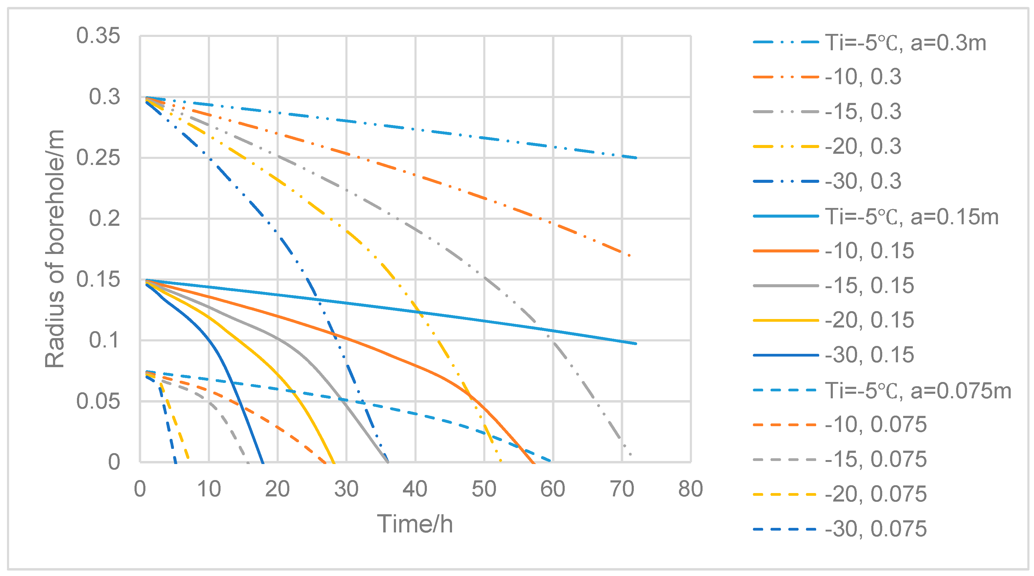
Figure 10 shows borehole closure in different surrounding temperatures and different initial borehole radii, and if the radius of the borehole is 0.3 m, the borehole would close to 0.15 m after 24 h if the surrounding temperature of the ice is −30 °C, while it will be closed to 0.284 m after 24 h if the temperature is −5 °C. If the time of the hole to be open with the minimal diameter is not enough to finish drilling and observations, then reaming must be included in the working procedure.
4. Recommendations and Example
We suggest the following response protocol at the designing stage. First, independent variables (target depth and potential temperature distribution of ice) have to be furnished. Then, the desired controlled outcome variables must be carefully analyzed and set: the minimal diameter of the drilled borehole, required rate of penetration, and required time for the hole to be kept open. At this stage, it is also necessary to choose a water supply method and to draw a general concept of the hot-water drilling system including the basic layout of the system, the main components, and the interconnections. Finally, the main parameters of hot water drilling systems, i.e., flow rate, delivery pressure, and temperature of the delivered water, can be estimated.
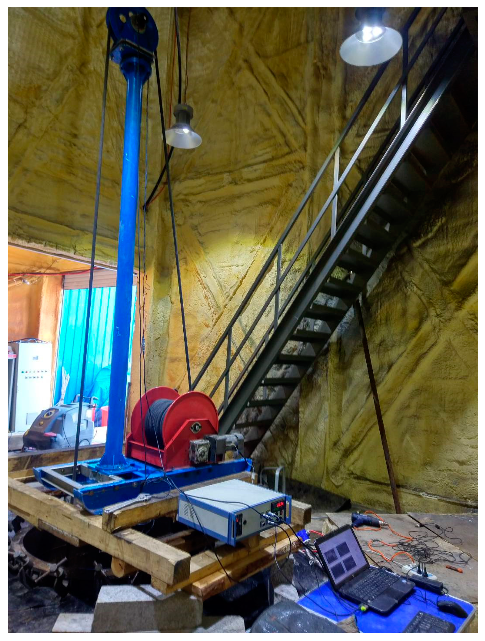
The proposed method was successfully used to choose parameters of a Jilin University (JLU) shallow hot water ice drilling system intended to make shot holes and temperature measurements in Antarctic margins (Table 1, Figure 11). To pump and heat the water, it was decided to use a commercial high-pressure washer, Kärcher HDS 6/14C, that can deliver water at a temperature in the range of 80–155 °C and a flow of 4–10 L min−1 at a pressure as high as 14 MPa [15]. This unit generally meets estimated conditions (required temperature 80 °C and flow rate 10 L min−1) and requires little maintenance. Even though it is quite heavy (108 kg), bulky, and not dismountable, its use can save the time required for the design and testing of the original system. The estimated pressure drop through the 100 m hose with an inner diameter of 22 mm is 1 MPa at the rate of 10 L min−1. The remaining pressure loss (up to 9 MPa) is attributed to the local hydraulic resistances at various parts of the drill circulation system (mainly, in the nozzle).
Lab tests showed that the system, in general, worked adequately. Under the hot water flow rate of 10 L min−1 with a temperature of 60 °C, the 1.8-mm and 2-mm nozzles created 98–114 mm diameter boreholes at a penetration rate of 34–37 m h−1. The required rate of penetration was set at 30 m h−1, with a minimal diameter of the drilled borehole of 80 mm.
5. Conclusions
The presented method allows one to obtain the main parameters of hot-water drilling systems that are essential for choosing pumps, boilers, hoses, valves, and other surface and downhole equipment. To drill as fast as possible, to create a borehole as large as possible, and to save fuel consumption for target depth, higher flow rates and higher temperatures are required. However, a larger flow rate leads to the use of bulky equipment as well as logistical issues. The choices of flow rate, temperature of water, and fuel consumption should be decided together. Assuming the initial temperature of hot water as 90 °C, using pumps with a rated flow rate of 50 L min−1 has a target depth limitation of 600 m, 100 L min−1–1200 m, and 150 L min−1–1900 m. If the target depth is 2000 m, the initial temperature must be at least 80 °C at a 200 L min−1 flow rate. In most cases, several estimation cycles must be made before rational parameters are found.
In most cases of intermediate or deep hot-water drilling, the friction pressure losses play critical roles in the required delivery pressure of hot water flow, and they mostly depend on the length of the hose, hose diameter, and flow rate, while the local pressure losses may be much more important for shallow drills to provide a strong contact upon bottom ice. The length of time that a borehole remains sufficiently open depends on the surrounding ice temperatures and initial borehole radius. This should be carefully considered at the beginning of the design project because the hole cannot be left to refreeze until its diameter becomes less than the size of the drill stem or the instrumentation being lowered through the hole.
Author Contributions
Conceptualization, P.T.; Formal analysis, G.L.; Funding acquisition, Y.Y.; Investigation, J.H.; Resources, G.L., A.L. and D.F.; Supervision, P.T. and R.W.; Visualization, D.G.; Writing—original draft, G.L.; Writing—review & editing, P.T.
Funding
This study was conducted with the support of the National Science Foundation of China (Project Nos. 41476160 and 41706214), the Ministry of Science and Technology of China (Project No. 2016YFC1400300), the Program for Jilin University Science and Technology Innovative Research Team (Project No. 2017TD-24), and the Fundamental Research Funds for the Central Universities.
Acknowledgments
The authors would like to give thanks to anonymous reviewers for fruitful discussion and useful comments, and Xiaopeng Fan (Polar Research Center, Jilin University) for his generous providing of Figure 1c.
Conflicts of Interest
The authors declare no conflict of interest.
References
- Gillet, F. Steam, hot-water and electrical thermal drills for temperate glaciers. J. Glaciol. 1975, 14, 171–179. [Google Scholar] [CrossRef]
- Iken, A.; Röthlisberger, H.; Hutter, K. Deep drilling with a hot water jet. Z. Gletscherkd. Glazialgeol. 1976, 12, 143–156. [Google Scholar]
- Poplin, J.P.; Ralston, T.D.; Lawrence, W.S. A thermal ice drill for profiling thick multiyear ice. Cold Reg. Sci. Technol. 1987, 14, 1–11. [Google Scholar] [CrossRef]
- Tucker, W.B., III; Govoni, J.W. A portable hot-water ice drill. Cold Reg. Sci. Technol. 1987, 14, 57–64. [Google Scholar] [CrossRef]
- Thorsteinsson, T.; Elefsen, S.Ó.; Gaidos, E.; Lanoil, B.; Jóhannesson, T.; Kjartansson, V.; Marteinsson, V.; Stefánsson, A.; Thorsteinsson, T. A hot water drill with built-in sterilization: Design, testing and performance. Jökull 2008, 57, 71–82. [Google Scholar]
- Tsutaki, S.; Sugiyama, S. Development of a hot water drilling system for subglacial and englacial measurements. Bull. Glaciol. Res. 2009, 27, 7–14. [Google Scholar]
- Craven, M.; Elcheikh, A.; Brand, R.; Jones, N. Hot water drilling on the Amery Ice Shelf—The AMISOR project. Mem. Nat. Inst. Polar Res. 2002, 56, 217–225. [Google Scholar]
- Makinson, K.; Anker, P.G.D. The BAS ice-shelf hot-water drill: Design, methods and tools. Ann. Glaciol. 2014, 55, 44–52. [Google Scholar] [CrossRef]
- Rack, F.R.; Duling, D.; Blythe, D.; Burnett, J.; Gibson, D.; Roberts, G.; Carpenter, C.; Lemery, J.; Fischbein, S. Developing a hot-water drill system for the WISSARD project: 1. Basic drill system components and design. Ann. Glaciol. 2014, 55, 105–114. [Google Scholar] [CrossRef]
- Benson, T.; Cherwinka, J.; Duvernois, M.; Elcheikh, A.; Feyzi, F.; Greenler, L.; Haugen, J.; Karle, A.; Mulligan, M.; Paulos, R. IceCube Enhanced Hot Water Drill functional description. Ann. Glaciol. 2014, 55, 105–114. [Google Scholar] [CrossRef]
- Siegert, M.J.; Makinson, K.; Blake, D.; Mowlem, M.; Ross, N. An assessment of deep hot-water drilling as a means to undertake direct measurement and sampling of Antarctic subglacial lakes: Experience and lessons learned from the Lake Ellsworth field season 2012/13. Ann. Glaciol. 2014, 55, 59–73. [Google Scholar] [CrossRef]
- Browning, J.A.; Bigl, R.A.; Sommerville, D.A. A Hot-water drilling and coring at site J-9. Ross Ice Shelf. Antarct. J. US 1979, 14, 60–61. [Google Scholar]
- Engelhardt, H.; Kamb, B.; Bolsey, R. A hot-water ice-coring drill. J. Glaciol. 2000, 46, 341–345. [Google Scholar] [CrossRef] [Green Version]
- Greenler, L.; Benson, T.; Cherwinka, J.; Elcheikh, A.; Feyzi, J.; Karle, A. Modeling hole size, lifetime and fuel consumption in hot-water ice drilling. Ann. Glaciol. 2014, 55, 115–123. [Google Scholar] [CrossRef]
- Talalay, P.; Liu, G.; Wang, R.; Fan, X.; Hong, J.; Gong, D.; Liu, B.; Liu, A.; Sysoev, M. Shallow hot-water ice drill: Estimations of drilling parameters and testing. Cold Reg. Sci. Technol. 2018, 155, 11–19. [Google Scholar] [CrossRef]
- Taylor, P.L. A hot water drill for temperate ice. CRREL Spec. Rep. 1984, 84-34, 105–117. [Google Scholar]
- Humphrey, N.; Echelemyer, K. Hot-water drilling and borehole closure in cold ice. J. Glaciol. 1990, 36, 287–298. [Google Scholar] [CrossRef]
- Zotikov, I.A. The Thermophysics of Glaciers; D. Reidel Publishing Co.: Dordrecht, The Netherlands, 1986; 275p. [Google Scholar]
- Idelchik, I.E.; Ginevskiy, A.S.; Kolesnikov, A.V. (Eds.) Handbook of Hydraulic Resistance, 4th ed.; Begell House, Inc.: New York, NY, USA, 2007. [Google Scholar]
- Brater, E.F.; King, H.W.; Lindell, J.E.; Wei, C.Y. Handbook of Hydraulics, 7th ed.; McGraw-Hill: New York, NY, USA, 1996. [Google Scholar]
- Belvins, D.R. Applied Fluid Dynamics Handbook; Krieger Publishing Company: Malabar, FL, USA, 1984; pp. 41–87. [Google Scholar]
- Rohsennow, W.M.; Hartnett, J.P.; Cho, Y.I. Handbook of Heat Transfer, 3rd ed.; McGraw-Hill Companies, Inc.: New York, NY, USA, 1998. [Google Scholar]
- Hughes, K.G.; Langhorne, P.J.; Williams, M.J.M. Estimates of the refreezing rate in an ice-shelf borehole. J. Glaciol. 2013, 59, 938–948. [Google Scholar] [CrossRef]
- Yen, Y.-C.; Tien, C. Heat Transfer Characteristics of Melting and Refreezing a Drill Hole Through an Ice Shelf in Antarctica; CRREL Report; CRREL (The Cold Regions Research and Engineering Laboratory): Hanover, NH, USA, 1976. [Google Scholar]
Figure 1.
Examples of hot-water drilling systems: (a) BAS (British Antarctic Survey) lightweight hot-water drill for seismic survey, Pine Island Glacier, Antarctica, season 2006–2007 (Photo from personal communication: R. Stilwell, British Antarctic Survey); (b) shallow drilling with hot-water drilling system of Hydrological Service Division of the National Energy Authority, Iceland on the Langjökull ice cap, 2005 [5]; (c) overview of intermediate-deep AWI hot-water drill, Ekström ice shelf, Antarctica, January 2018; (d) hose reel and tower of IceCube deep hot-water drilling system, December 2008 (Photo from personal communication: J. Haugen from IceCube, 2008).

Figure 2.
General schematics of typical hot-water drill systems depending on approaches to obtain water for drilling and to heat/pump water, as well as configurations for the mast and sheave wheel: (a) surface runoff water at mountain glaciers and the Greenland Ice Sheet that melt in the summer with folded mast, heater, and pump; (b) water melted in containers or tanks from surface snow and ice with dismountable mast and heater/pump unit combined in high-pressure washer; (c) water from supplementary borehole drilled nearby and connected with the main borehole by a subsurface cavity, stationary mast, and series of heaters/pumps; (d) water pumped out directly from the drilled borehole with tower, crescent wheel, and series of heaters/pumps.

Figure 3.
Schematic diagram of hot water drilling process (Q is the mass flow rate of hot water, kg s−1; Z is the borehole depth, m; D is the mean diameter of borehole, m; T0 is the initial temperature of water, °C; Ti is the ice temperature, °C; Tf is the final temperature of the mixture of hot water and melted ice, °C; Tb is the bottom temperature of drilling water that sprays out of the nozzle, °C; dh and b are the hose diameter and wall thickness, respectively, m).

Figure 4.
Minimum flow rate vs. average borehole diameter at rate of penetrations (ROPs) of 30 m h−1 (a) and 60 m h−1 (b) and different bottom temperature of drilling water Tb.
Figure 4.
Minimum flow rate vs. average borehole diameter at rate of penetrations (ROPs) of 30 m h−1 (a) and 60 m h−1 (b) and different bottom temperature of drilling water Tb.

Figure 5.
Minimum flow rate vs. ROP to drill a hole with average diameters of 0.15 m (a), 0.3 m (b), and 0.6 m (c) at different bottom temperature of drilling water Tb.
Figure 5.
Minimum flow rate vs. ROP to drill a hole with average diameters of 0.15 m (a), 0.3 m (b), and 0.6 m (c) at different bottom temperature of drilling water Tb.

Figure 6.
Required delivery pressure of hot water flow vs. length of the hose at different hose diameters (a, 0.75″; b, 1″; c, 1.25″; d, 1.5″) and flow rates; local pressure losses are taken as 1 MPa.
Figure 6.
Required delivery pressure of hot water flow vs. length of the hose at different hose diameters (a, 0.75″; b, 1″; c, 1.25″; d, 1.5″) and flow rates; local pressure losses are taken as 1 MPa.

Figure 7.
Required initial temperature of hot water vs. target depth at different flow rates of hot water; bottom water temperature is taken constant as 50 °C (b = 11 mm, dh = 38 mm, k = 0.3 J s−1 m−1 K−1, and Cw = 4190 J kg−1 K−1).
Figure 7.
Required initial temperature of hot water vs. target depth at different flow rates of hot water; bottom water temperature is taken constant as 50 °C (b = 11 mm, dh = 38 mm, k = 0.3 J s−1 m−1 K−1, and Cw = 4190 J kg−1 K−1).

Figure 8.
Mean borehole diameter vs. ROP at different target depths (a, 2000 m; b, 1500 m; c, 500 m) and flow rates (b = 11 mm, dh = 38 mm, k = 0.3 J s−1 m−1 K−1, Ti = −20 °C, and Cw = 4190 J kg−1 K−1)
Figure 8.
Mean borehole diameter vs. ROP at different target depths (a, 2000 m; b, 1500 m; c, 500 m) and flow rates (b = 11 mm, dh = 38 mm, k = 0.3 J s−1 m−1 K−1, Ti = −20 °C, and Cw = 4190 J kg−1 K−1)

Figure 9.
Fuel consumption (diesel) vs. mean borehole diameter at different target depths and flow rates (b = 11 mm, dh = 38 mm, k = 0.3 J s−1 m−1 K−1, Ti = −20 °C, and Cw = 4190 J kg−1 K−1)
Figure 9.
Fuel consumption (diesel) vs. mean borehole diameter at different target depths and flow rates (b = 11 mm, dh = 38 mm, k = 0.3 J s−1 m−1 K−1, Ti = −20 °C, and Cw = 4190 J kg−1 K−1)

Figure 10.
Borehole closure time at different initial borehole radius and surrounding temperatures.

Figure 11.
JLU shallow, hot-water, ice-drilling system installed on the drilling testing facility (for more details see Talalay et al., 2018 [15]).
Figure 11.
JLU shallow, hot-water, ice-drilling system installed on the drilling testing facility (for more details see Talalay et al., 2018 [15]).


Table 1.
Estimated and chosen/tested parameters of Jilin University (JLU) shallow, hot-water, ice-drilling system.
Table 1.
Estimated and chosen/tested parameters of Jilin University (JLU) shallow, hot-water, ice-drilling system.
| Parameters | Estimated Parameters | Chosen/Tested Parameters |
|---|---|---|
| Target depth, m | 100 | NA |
| Minimal expected temperature of drilled ice, °C | −30 | NA |
| Minimal diameter of the drilled borehole, mm | 80 | 100–160 |
| Required/tested rate of penetration, m h−1 | 30 | 12–36 |
| Required/tested time for the hole to be kept open, h | 12 | 12–24 |
| Power consumption, L m−1 | 0.15 | −0.2 |
| Flow rate of hot water, L min−1 | 10 | 6–10 |
| Delivery pressure, MPa | 2–10 | 14 |
| Temperature of the delivered water, °C | 80 | 50–90 |
| Hose diameters, mm | 8 | 10 |
NA—not available.
© 2019 by the authors. Licensee MDPI, Basel, Switzerland. This article is an open access article distributed under the terms and conditions of the Creative Commons Attribution (CC BY) license (http://creativecommons.org/licenses/by/4.0/).
Share and Cite
MDPI and ACS Style
Liu, G.; Talalay, P.; Wang, R.; Yang, Y.; Hong, J.; Gong, D.; Liu, A.; Fan, D. Design Parameters of Hot-Water Drilling Systems. Water 2019, 11, 289. https://doi.org/10.3390/w11020289
AMA Style
Liu G, Talalay P, Wang R, Yang Y, Hong J, Gong D, Liu A, Fan D. Design Parameters of Hot-Water Drilling Systems. Water. 2019; 11(2):289. https://doi.org/10.3390/w11020289
Chicago/Turabian StyleLiu, Gang, Pavel Talalay, Rusheng Wang, Yang Yang, Jialin Hong, Da Gong, An Liu, and Dayou Fan. 2019. "Design Parameters of Hot-Water Drilling Systems" Water 11, no. 2: 289. https://doi.org/10.3390/w11020289
Note that from the first issue of 2016, this journal uses article numbers instead of page numbers. See further details here.