Numerical Research on the Resistance Reduction of Air Intake


College of Shipbuilding Engineering, Harbin Engineering University, Harbin 150001, China
*
Author to whom correspondence should be addressed.
Water 2019, 11(2), 280; https://doi.org/10.3390/w11020280
Submission received: 13 December 2018
/
Revised: 27 January 2019
/
Accepted: 1 February 2019
/
Published: 6 February 2019
(This article belongs to the Special Issue Applications of Computational Fluid Dynamics for Marine and Offshore Engineering)
Abstract
:In order to investigate the drag-reducing effect of air intake, forward motion of planing trimaran models in calm water were simulated for Froude numbers ranging from 3.14–5.87. The hull body motion is implemented by coupling the fluid solver with motion solver. Numerical results were compared with the experimental data and showed good agreement. Contrastive calculations of models with and without air intake show that the air intake presents evident drag-reducing effect when Froude number is above 4.49, the cambered configuration of air intake could amplify air cavity and thus decrease fractional resistance. CFD incremental studies were subsequently carried out for the camber of air intake, it is found that the model with chamber-shortened air intake shows the worst resistance performance, while enlarging air intake chamber could reduce resistance at Froude numbers between 4.06 and 4.97.
1. Introduction
Trimaran planing boats are a new type of boat whose main structure consists of a capacious main hull and two long and thin demi-hulls. They differ from the conventional planing boat in having a tunnel that is ventilated as the hull body is lifted from the water, creating an aerodynamic lift that acts on the tunnel surface [1]. Therefore, the hull behaviours of planing trimaran boats at high speeds are the result of the coupled effect of aerodynamic and hydrodynamic lift. Furthermore, because the tunnel is ventilated at high speed, most of the drag force acts on the main hull and the resistance created by the tunnel is lower.
To improve the trimaran resistance performance at high speeds, the resistance reduction method of introducing steps on the main hull bottom has been adopted; this method could increase the planing efficiency because of the lower aspect ratio of every planing surface and the creation of an air cavity after the steps which decrease the wetted surface area. The drag-reducing effects of steps have been proved by numerical simulations and towing tests, the latter could date back to the 1950s. Rodstrom and Gregory have studied the stepped planing boat hydrodynamic performance using a model towing test [2]. Taunton et al. have developed a new series of planing hull [3,4]; based on the survey of the main dimensions of existing planing crafts, contrast tests for stepped and non-stepped models were performed. Compared with towing test, the numerical simulation is fast and economical because there is no need to prepare ship model and towing tank [5]. With the advances of computational power, computation fluid dynamics (CFD) has become an important approach for analysis of hull performance for lower cost and time consumption compared to experimental tests. Lotfi et al. investigated the C series stepped hull of Taunton and their focus was on the numerical accuracy [6]. The C series models were also studied using CFX by Veysi and Bakhtiari [7,8]. Azcueta and Rousselon proposed a numerical method that coupled the solving of the governing and motion equations, using which the motions of a stepped planing boat in calm and rough water were simulated [9]. Sheingart and Faison studied Dynaplane’s hydrodynamic performance by STAR-CCM+ [10,11]; the wetted surfaces, pressure and velocity distributions around the step are analysed. Agostino De Marco et al. addressed the experimental and numerical study of a stepped planing hull; validation and verification studies were performed to improve the numerical accuracy [12].
For the planing trimaran, in recent years, several numerical investigations have been conducted on this novel hull form or certain other tunnel-type planing crafts. Ghassabzadeh and Ghassemi established a tunnelled planing hull model using polynomial function and Non-uniform Rational B-Spline (NURBS) algorithm and then, the 2-Degree of Freedom (DOF) motion in calm water was simulated by Fluent using dynamic mesh [13]. Yousefi et al. also utilized Fluent to compare the resistance and trim between mono-hull and trimaran in the same dimension. Their calculations showed that the drag of trimaran at 60 knots is decreased approximately 14% [14]. Based on the conclusion of Yousefi, Moghadam discussed the influence of tunnel aperture on resistance; it was found that the model with small tunnel aperture possesses the best resistance performance [15].
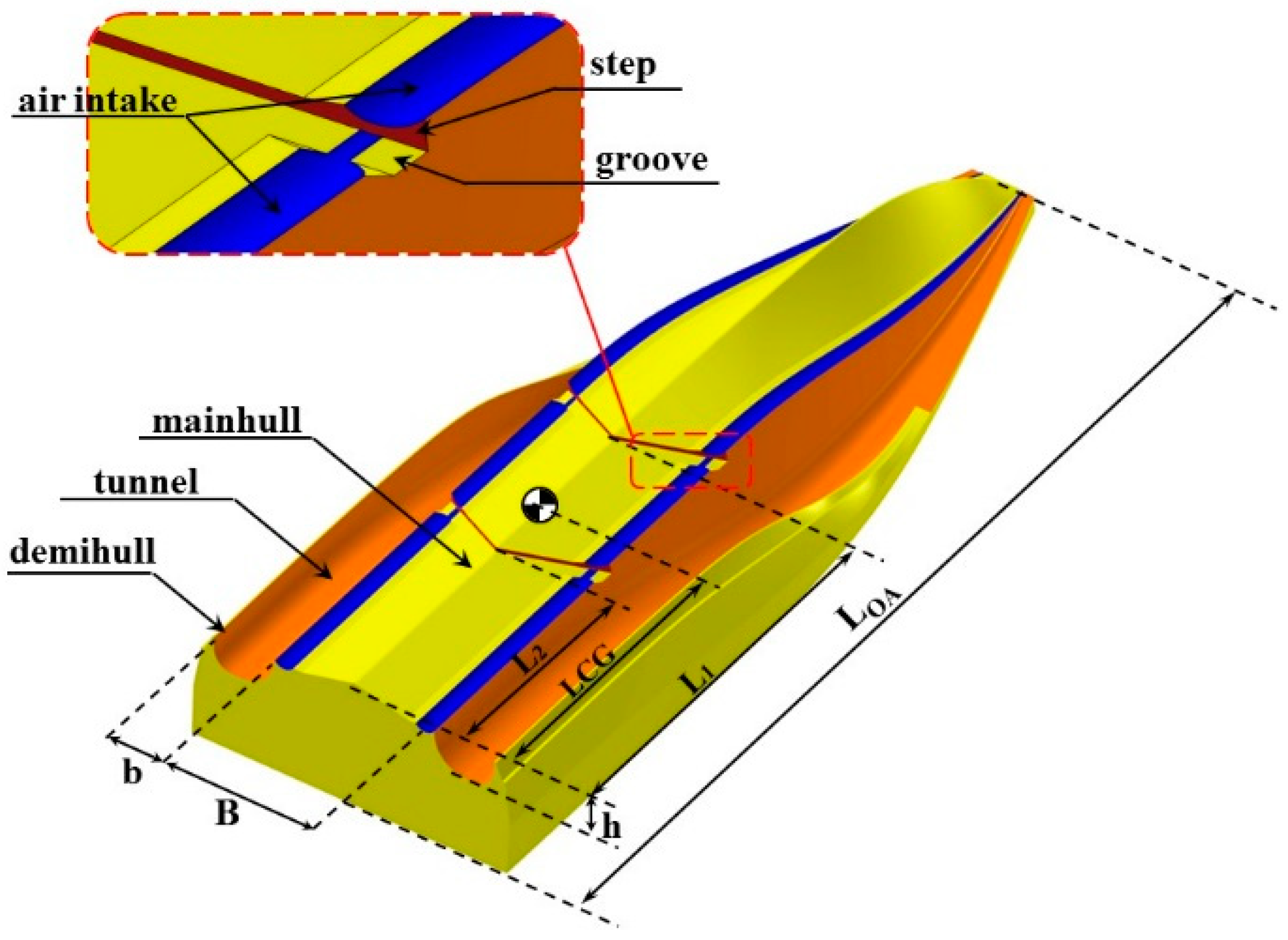
In this article, to further reduce the resistance of the stepped main hull of a planing trimaran, a new measure is introduced, as shown in Figure 1. A pair of grooves, named air intake, are notched along the chine of the main hull. The hydrodynamic performance of step could be improved by means of these grooves. Longitudinally, the air intake extends from bow to stern and breaks at the steps.
The rest of the paper is organized as follows: first, the hull geometry of a planing trimaran and the design of the air intake are described in detail, followed by a brief introduction of the numerical setup and validation of numerical results. Then, contrast calculations of models with and without air intake are carried out to analyse the drag-reducing mechanism. Furthermore, the hydrodynamic performance of models with different air intake cambers were tested to determine the influence of camber on resistance performance.
2. Numerical Setup
2.1. Physical Description of Hull Geometry
As shown in Figure 1, the hull geometry of a planing trimaran consists of a hard chine main hull in the middle and two thin demi-hulls arranged on the sides. The main hull provides most of the buoyancy and hydrodynamic lift during forward motion, while the demi-hull is designed to keep the directional stability and conduct the air flow in the tunnel region. Two V-type backward steps longitudinally cut the main hull planing surface into three parts. The air intake is located at the left and right ends of each planing surface. To improve the air inflow after the step, transverse grooves are cut along the step line. The main dimensions of the model are listed in Table 1.
2.2. Mathematical and Numerical Method
During simulation, the governing equation of incompressible viscous flow is described by the Reynold–Averaged Navier–Stokes Equations (RANSE) which is the most widely used method in engineering. The equation is described as following,
where denote the time averaged velocity components, are the fluctuations of the velocity components,
is the time averaged pressure, is dynamic viscosity coefficient, t is time and are unit vectors in directions of i and j. To close this set of equations, the Shear Stress Transport (SST) turbulence model is used.
The transported variable of turbulent kinetic energy, k, is defined as following,
The second transported variable ω is defined as following,
represent the turbulent kinetic energies due to the average velocity gradient, are turbulent dissipation terms, denote the effective diffusion terms, is the orthogonal divergence term.
The volume of fluid (VOF) model is applied to track the location and evolution of the free surface [16]. The basic idea of the VOF is to define the marking function α in the discrete domain and to determine the value of the volume function in one grid according to the volume of the fluid in it: When the value of α is 1 or 0, there is only one fluid in the grid. When the value of α is between 0 and 1, it is occupied by two kinds of fluids, that means there is a free surface in the grid. α satisfies the following transport equation,
Other than the solving process of traditional ships, the planing boat is mainly supported by the hydrodynamic lift during planing. The hull behaviour (pitch and heave) at high speed is very different from that in static floating and has significant influence on the resistance performance. Therefore, a 6-DOF motion equation is introduced here and the moment of hull body is implemented by the coupling of the motion and flow solver.
After the initial flow field solving, the force and moment acting on the hull body, including the shear stress, pressure caused by interaction of model and flow field and model gravity, could be acquired by the equations below:
where are the shearing force and pressure respectively, is the unit vector of the pressure. denotes the outer normal vector of the model surface, and stand for displacement of mesh nodes on hull surfaces and displacement of the gravity centre. S represents the hull surfaces. The linear displacement and angular displacement can be calculated by using:
where and are defined as the force and moment vector acting on the model, m denotes the mass.
In this article, the simulation is carried out using ANSYS-CFX, where the detailed solving process is a coupling iterative procedure. ANSYS-CFX is one of the most widely used CFD software at present. It discretizes the govern equations by the finite volume method and integrates each grid in the domain by solving the differential equations, thus the discrete algebraic equation is obtained and used in solution.
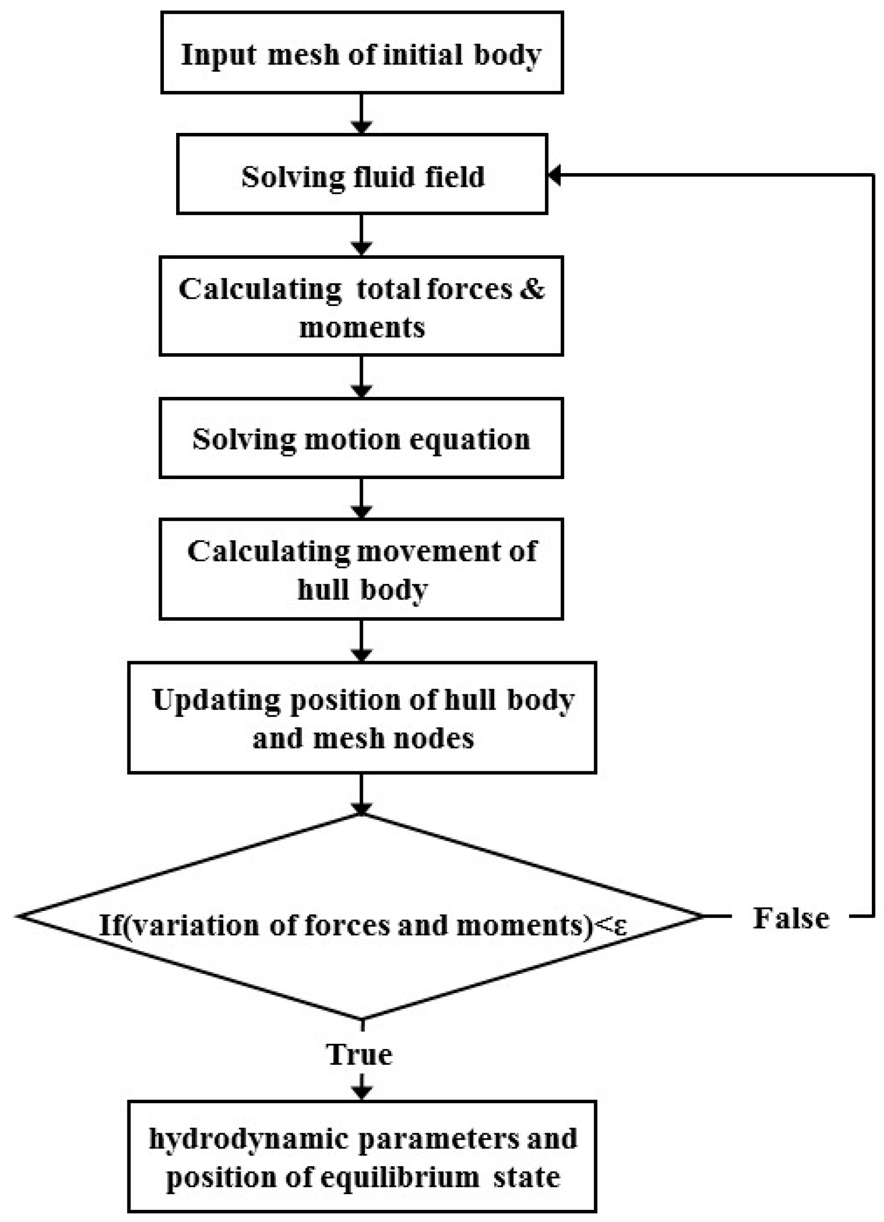
As shown in Figure 2, after solving the initial mesh, pressure and shear stress field around hull body are acquired and the total force and the moment can be calculated by integrating them on hull surface according to Equations (5) and (6). Using Equations (7) and (8), the hull displacement is solved and the hull motion is subsequently modelled through the mesh node moving to a new position. The next iteration of flow solver is carried out on the new mesh. When the variations of calculated forces and moments approach zero, the hull body is considered to achieve the balance state and the calculation process is terminated.
2.3. Domain and Boundary Conditions
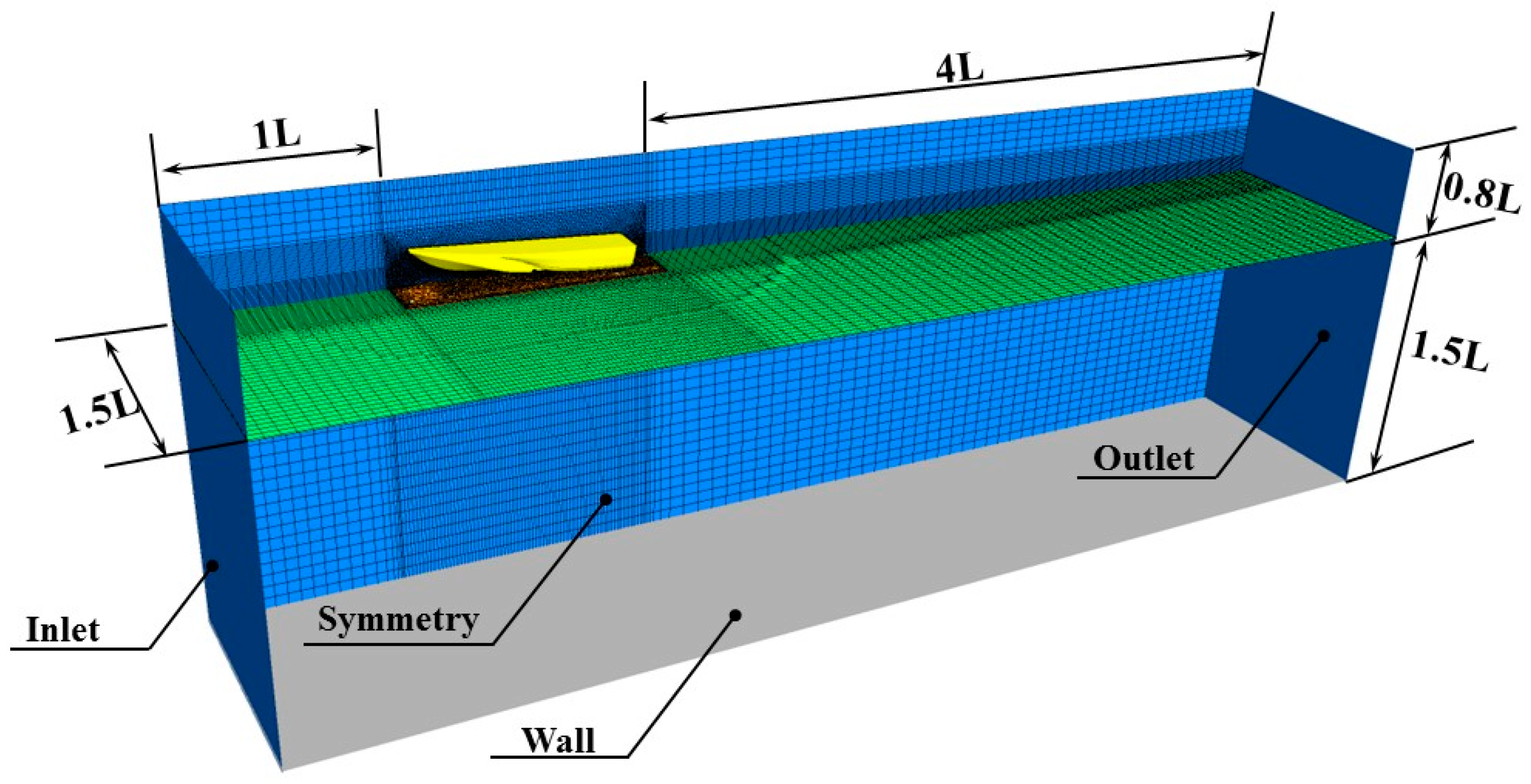
The domain dimensions and boundary conditions are specified in Figure 3. Considering the symmetrical characteristic of the flow field, only half of the hull body is modelled. The boundary conditions are specified as follows: the hull body is a moving boundary and a no-slip condition is imposed on the hull surface; free-slip condition is applied to the top, side and bottom walls; symmetry condition is used for the hull centre plane; the flow velocity at inlet is defined as the tested speed; at the outlet, the hydrostatic pressure defined as a function of water level height is applied; furthermore, the initial location of the free surface is determined by defining the volume fraction function of water and air at the inlet and outlet.
2.4. Mesh Generation
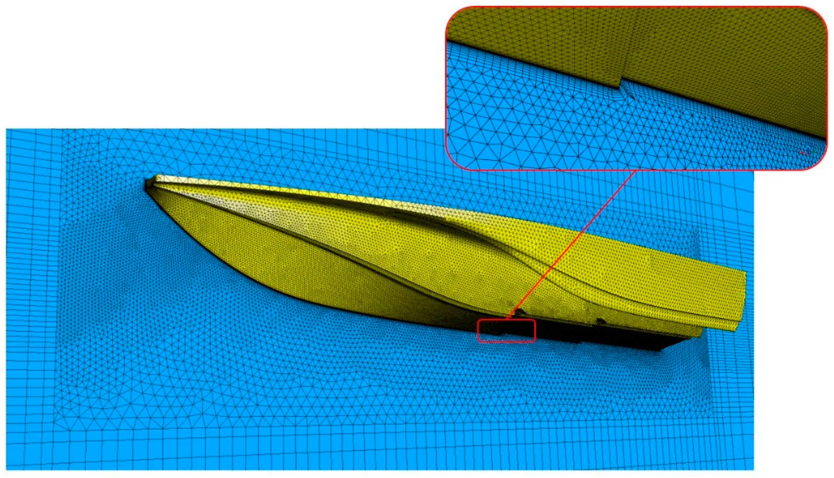
The mesh generation in this study is accomplished using ANSYS ICEM, as shown in Figure 4. The calculation domain is discretized using structured and unstructured meshes. Considering the complex geometrical characteristics of the hull, a mesh with triangular elements is generated on the hull surface and the boundary layer is refined with prism elements created through extending the surface mesh node. The region around the boat is filled with tetrahedral elements, while in the far field, a structured mesh with hexahedral elements is generated to reduce the number of elements.
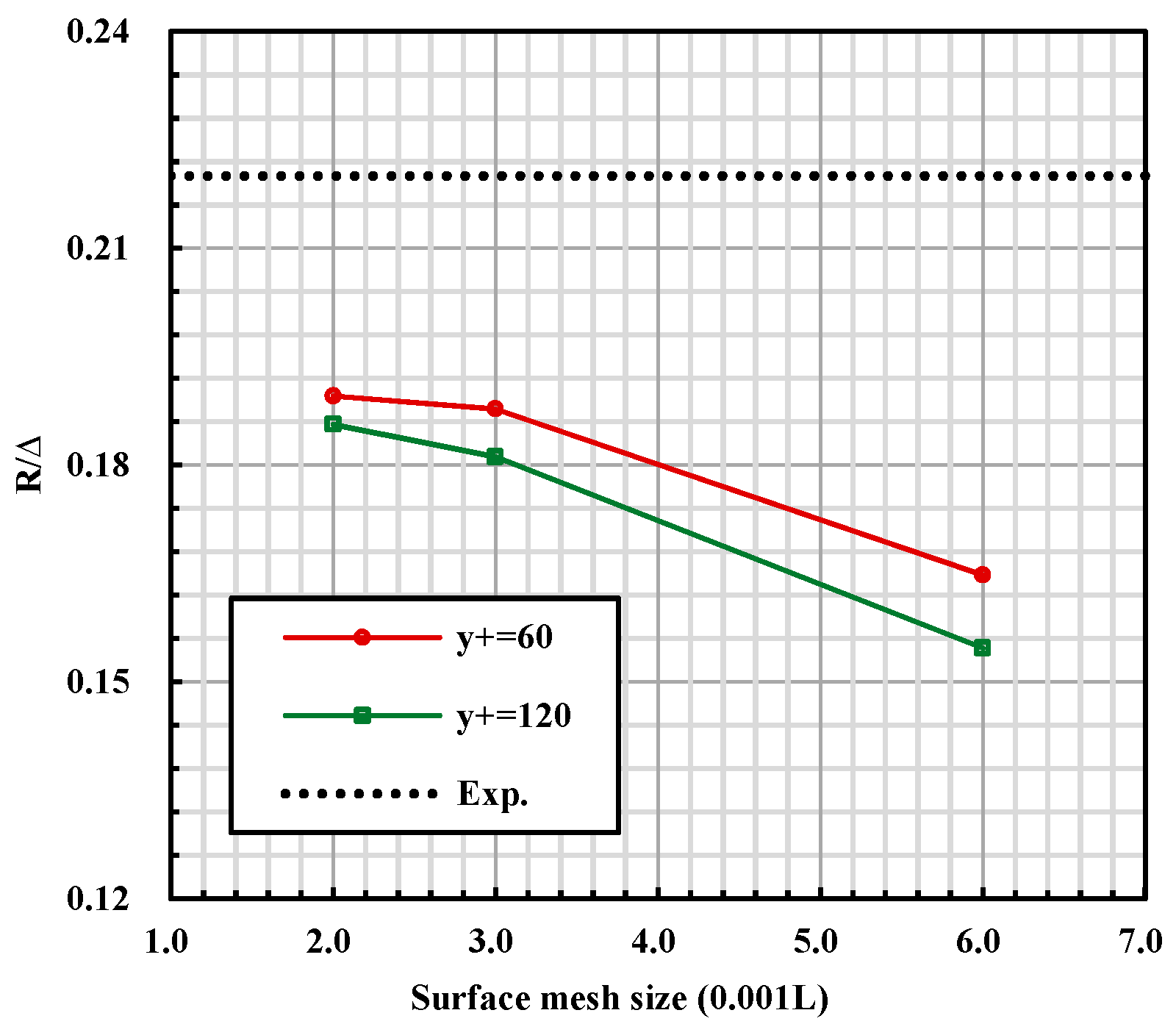
The mesh size plays an important role in the calculation procedure, a fine mesh can always bring credible results in ANSYS CFX but at the same time increases the computational cost and time consumption due to the large element number. Therefore, to determine the mesh size with acceptable numerical accuracy and element number, mesh convergence studies are carried out for the two models at the volume-based Froude number of 5.73. Surface mesh on hull bottom and the adjacent volume mesh are gradually refined since the flow around planing surface has direct influence on hydrodynamic characteristic of the step and the tunnel. The surface mesh size tested in current investigation are 0.002, 0.003 and 0.006, respectively, while, non-dimensional height of the first prism layer (y+) is decreased from 120–60. The calculated resistance of different mesh plans is plotted as function of surface mesh size in Figure 5, the experimental resistance is also presented to evaluate the numerical accuracy. It can been seen that the mesh plan with lower y+ and smaller surface mesh generally gives results with higher precision, when the surface mesh size is as fine as 0.003, further refinement shows no more improvement in numerical accuracy. Therefore, mesh independence of the numerical method is satisfied and the mesh plan with y+ of 60, surface mesh size of 0.003 is selected for the following numerical simulations. In this case, the total elements number is about .
2.5. Validation of the Method
In this study, several trimaran models with various geometry characteristics are investigated and compared to clearly capture the difference between each model. The numerical method should be validated to ensure the accuracy. A validation procedure is presented based on the experiment result of the model shown in Figure 1. This test has been carried out in the towing tank of the China Special Vehicle Research Institute (also named No. 605 Research Institute, a subsidiary of AVIC (Aviation Industry Corporation of China, Ltd.)) and its dimensions are 510 m × 6.5 m × 6.8 m in length, width and depth, respectively.
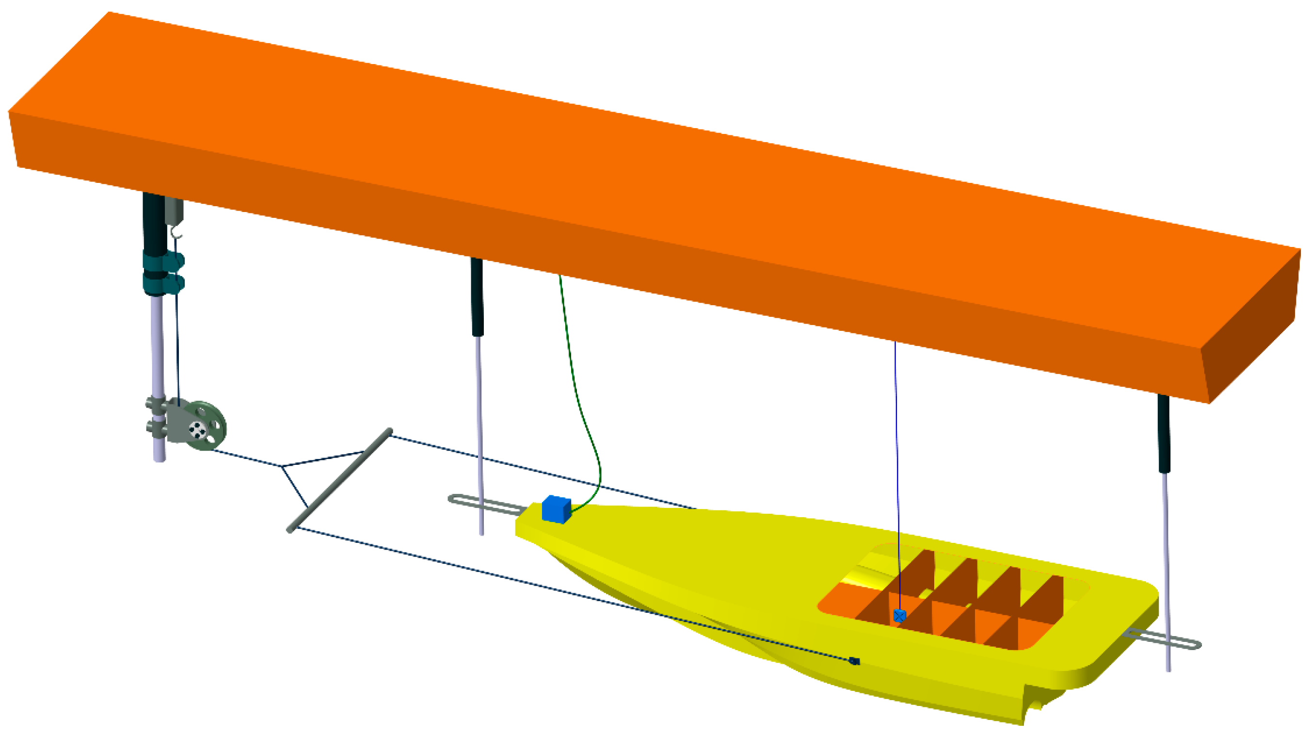
The towing test model has the same geometric characteristics as the numerical model. The model has been polished and painted before the test in order to ensure the smoothness of the surface. As Figure 6 shows, the model is driven by a carriage platform and has only two degrees of freedom (heave and pitch). The measured records are resistance, trim angle and heave are detected by a dynamometer, electronic angle sensor and cable-extension displacement sensor respectively.
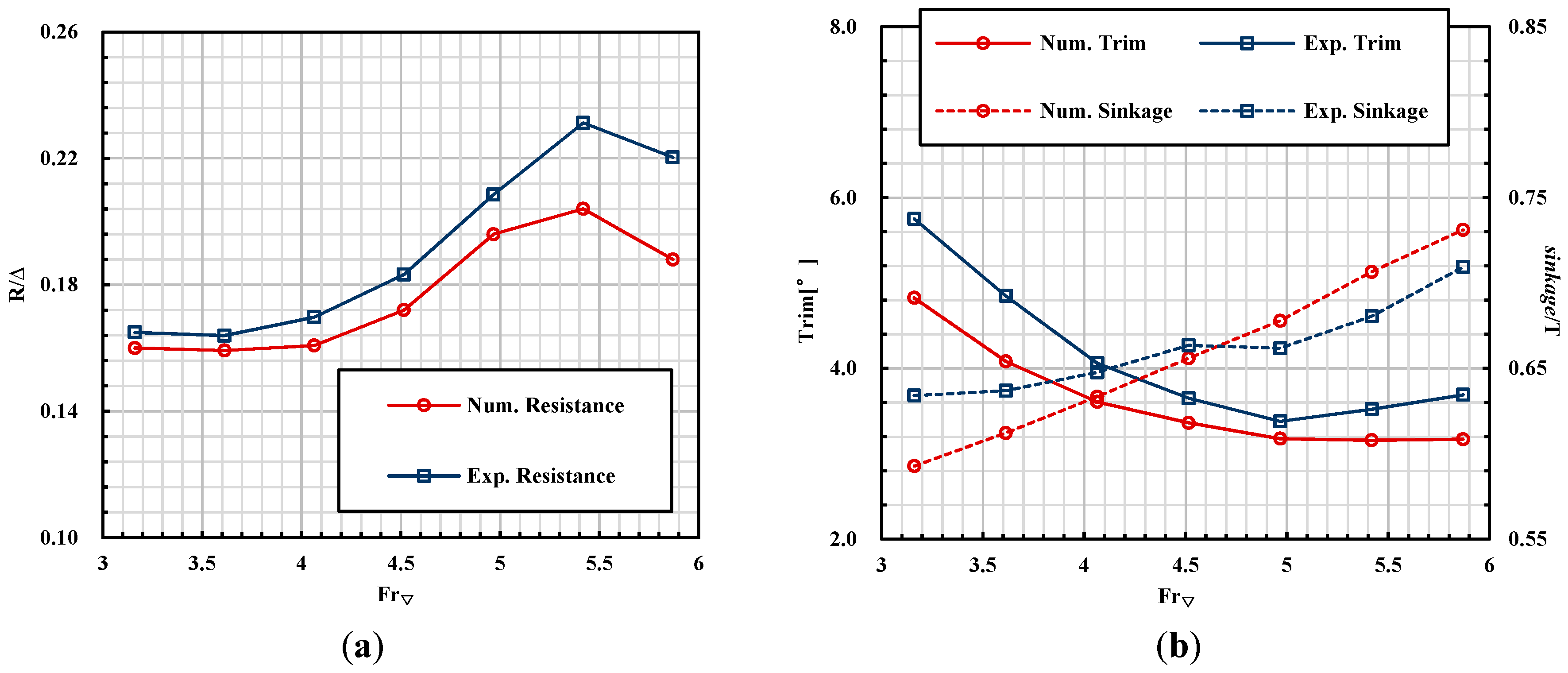
In Figure 7 and Table 2, the calculated results are compared with the experiment data, of which the non-dimensional resistance is defined by the ratio of the resistance to hull weight (R/Δ) and the non-dimensional sinkage is defined as sinkage/T. The volume-based Froude number is chosen to represent the towing speed, which is defined by the equation below:
where V is the model velocity, g is the acceleration of gravity and ∇ is the volumetric displacement of the hull. The working condition discussed here ranges from Froude number of 3.16 to 5.87, in which the hull body has been entirely planing.
It can be seen that the calculated resistance shows good agreement with the experiment when the Froude number is below 4.97, whereas after that, the error increased. The average errors in trim angle, sinkage are 11.62% and 3.29%, respectively. It seems that the average error of trim angle is larger, while in fact, the average value difference is only 0.5°. It can also be observed that the experiment data is larger than calculated, mainly because the numerical method adopted in this study is not sufficient to capture the spatter that acts on the tunnel and hull and therefore, the corresponding friction resistance cannot be accounted for. However, it still reveals the variation tendency of resistance and speed and the drag peak is also satisfactorily predicted. Therefore, the validity of the numerical method is proved.
3. Drag-Reducing Effect and Mechanism
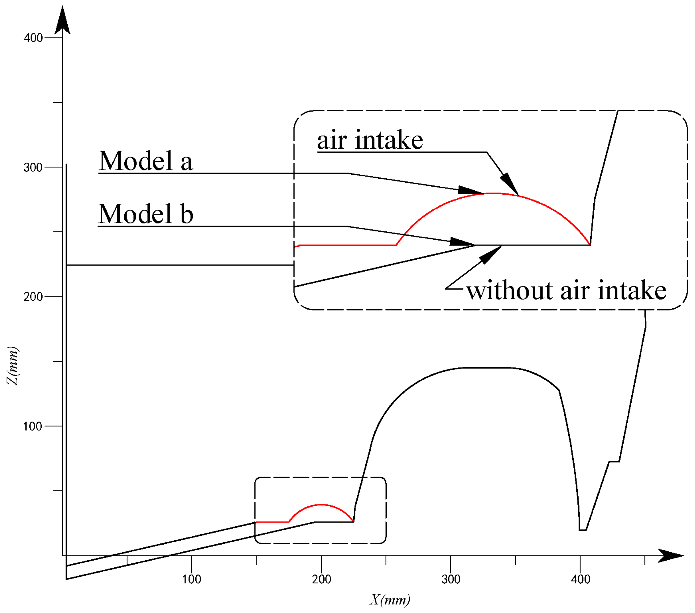
To verify the resistance reduction effect, a new model with no air intake is built and the main hull beam, the deadrise angle and chine width are kept as the original model. For the purpose of discussion, the two models are named as model a and model b respectively. Figure 8 shows the transverse geometry feature of each model in the middle of the boat.
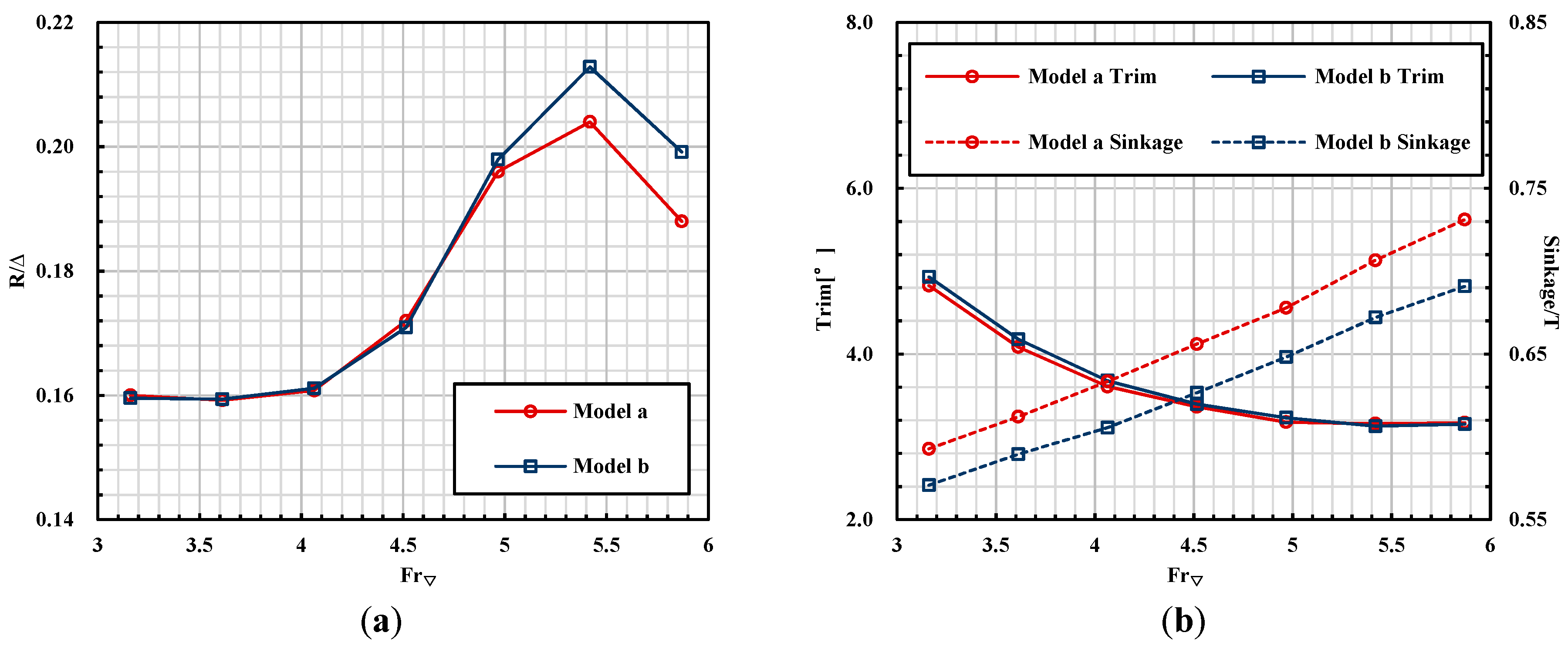
Using the same computation setting and mesh generation, contrast calculations are carried out for the two models. As shown in Figure 9, the resistance, trim angle and sinkage are plotted as functions of Froude number. It can be seen that, in terms of hull behaviour, the trim angle shows no evident difference but the sinkage of model b is slightly less than that of model a at the calculated speeds. When the Froude number is above 4.52, the model with air intake presents superiority in resistance performance, as the speed is increased, the drag-reducing effect of air intake becomes significant, at the maximum speed the total resistance is decreased by 5.9%. That is to say the design of the air intake is efficient and helpful at higher speed.
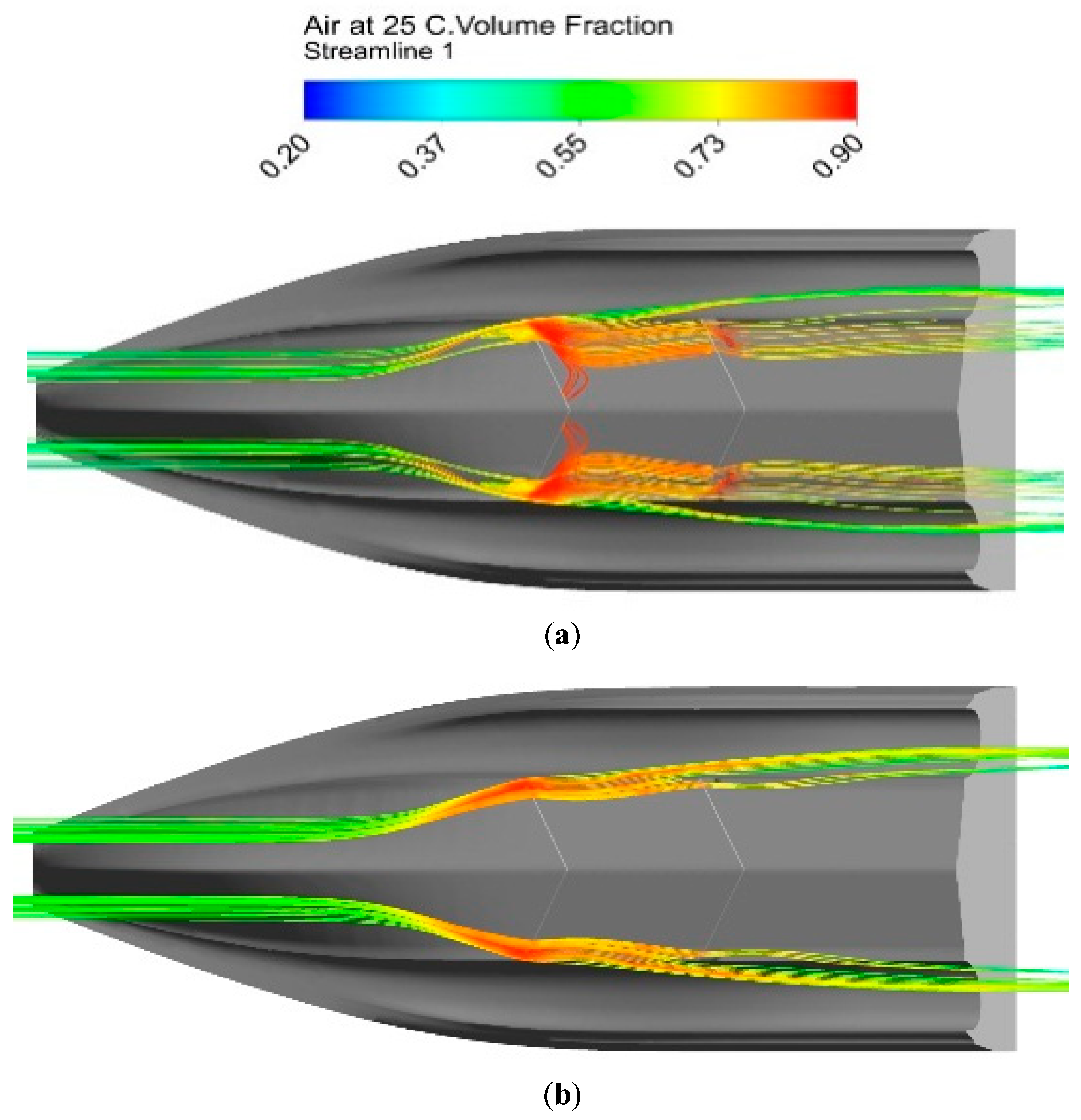
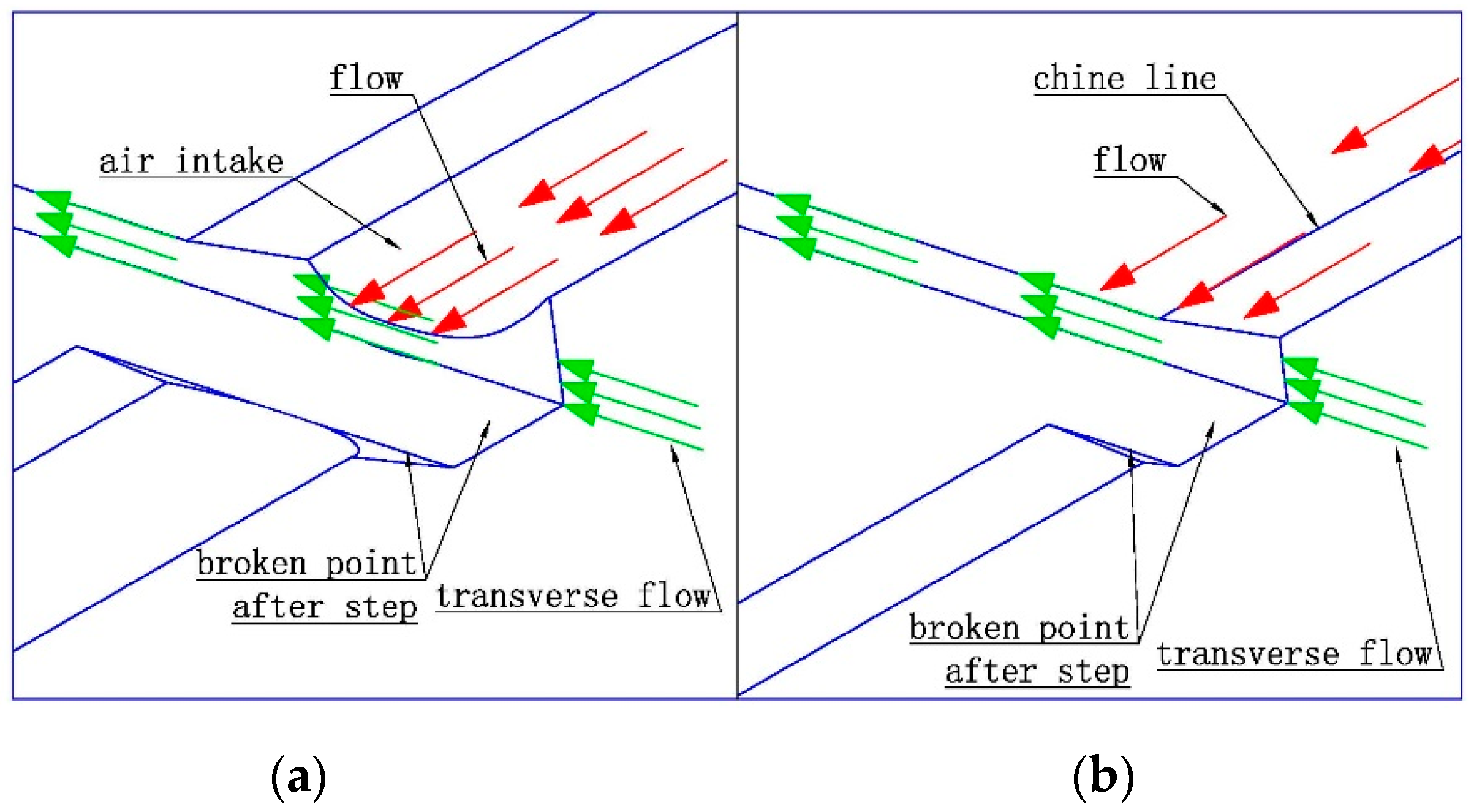
The air cavity behind step could reduce the wetted area on the planing surface, thus the fractional resistance decreases. The formation of the air cavity is mainly due to the flow separation at step locations, which creates a low pressure region after the step. In this condition, the air around the hull body is sucked onto the hull bottom through the groove after the step. Therefore, transverse air flow should be clearly observed at the grooves. To illustrate the influence of air intake on transverse air flow, the streamline (coloured by air volume fraction) distributions around the main hull chine of the two models are compared in Figure 10. To precisely capture the flow characteristics in the step region, the control points of streamlines are located at the end of the first planing surface (wrapping the air intake for model a and suspending on the chine for model b). The normal distance between these points and the hull surface is very small (approximately 1 mm). It can be seen that, without air intake, the streamlines distribution of model b is regular and tends to spread outside; while an evident transverse disturbance can be observed for model a, the streamlines extend inward after getting through the step and air turbulence is created and distributes along the step line. This is because the cambered configuration of the air intake could contain air and lead the air flow to intersect with the transverse flow originating from the groove. The flow mechanism is specified in Figure 11. For the conventional chine form, the air flow would just get over the step and no intersection happens with the transverse flow.
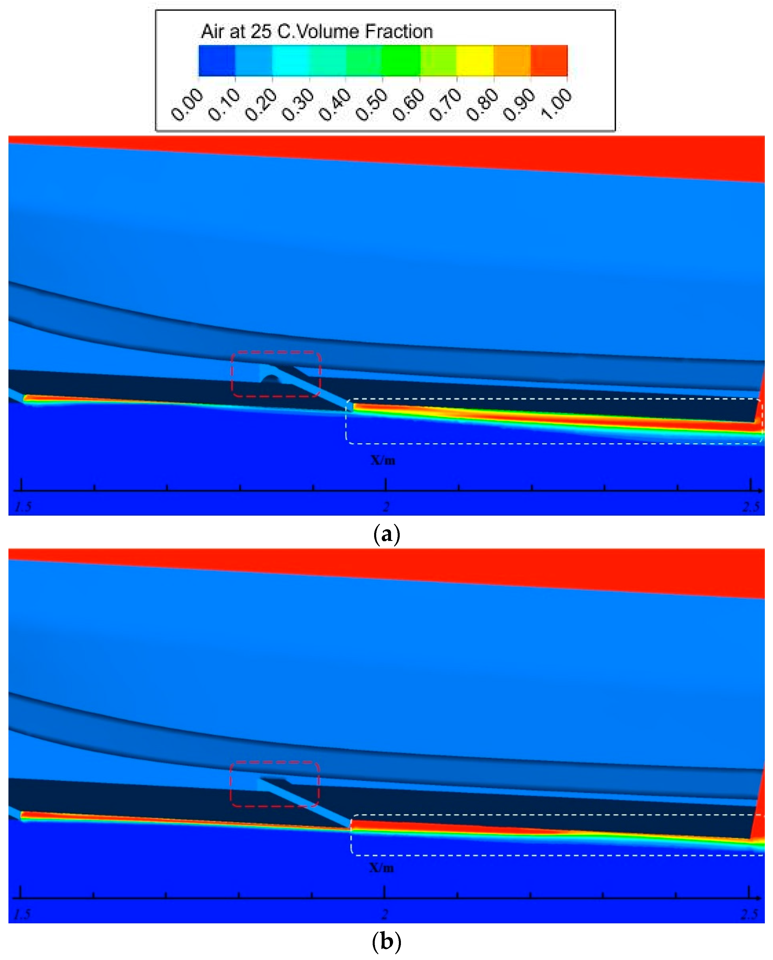
As above, the air in air intake could be partly conducted onto the hull bottom owing to the transverse flow behind step. It seems that, benefiting from air intake, the air in front of hull body is injected onto the hull bottom during navigation. That would affect the formation of the air cavity directly. Figure 12 shows the comparison of the air volume fraction in the centre plane at the Froude number of 5.87. It can be seen that the air cavity of model a is larger than model b just because of the air injection from air intake; correspondingly, the wetted area on planing surface after the step is smaller and the drag-reducing effect of the step is more obvious.
4. Influence of Camber on Hydrodynamic Performance
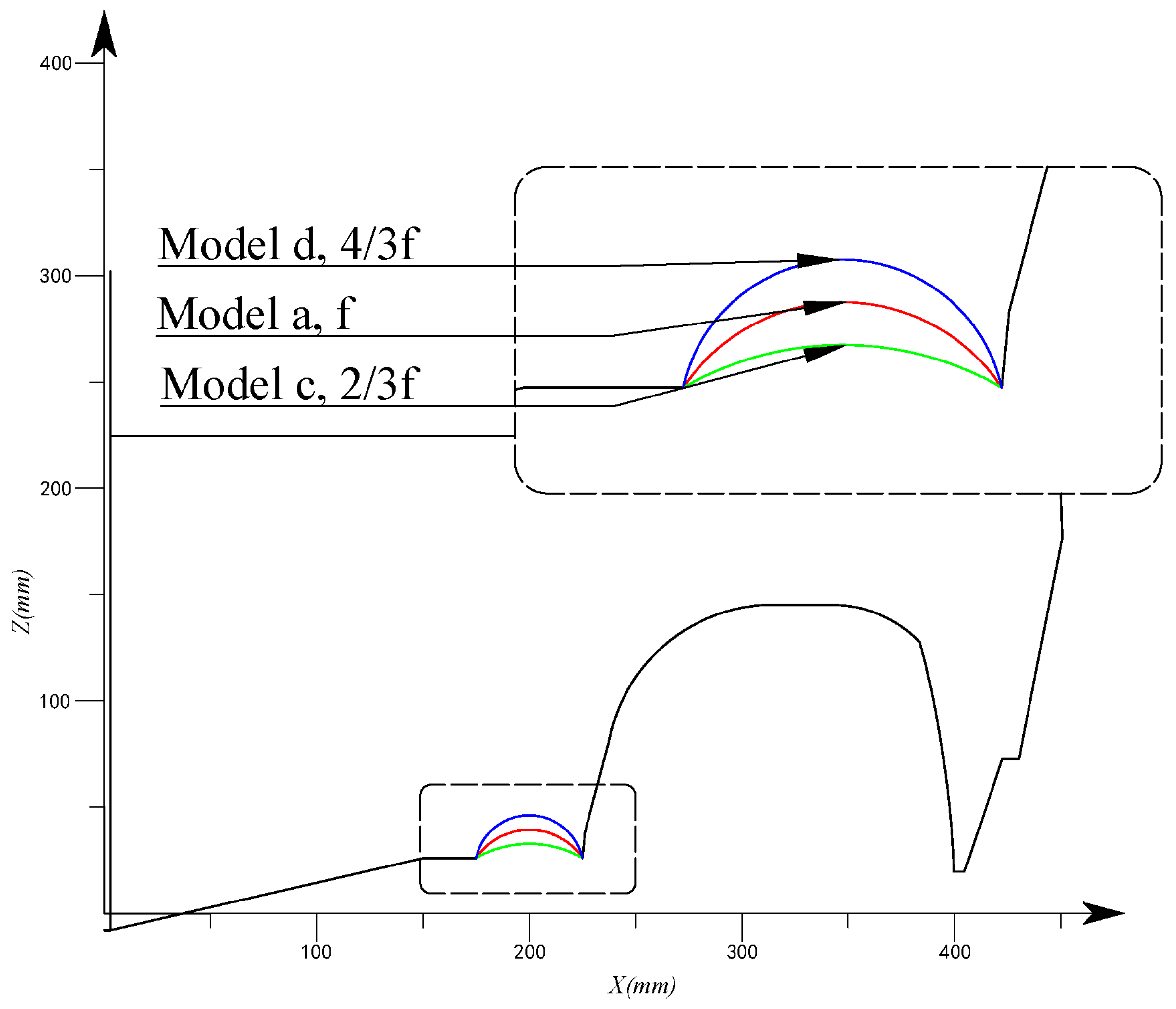
As the key to the drag-reducing effect of air intake is camber’s concave geometrical feature, it is necessary to discuss the impact of camber on resistance performance. Two new models, model c and model d, are built, the air intake cambers () of which are enlarged and shortened by , respectively. The comparison of cross-sections of the original and modified models is shown in Figure 13.
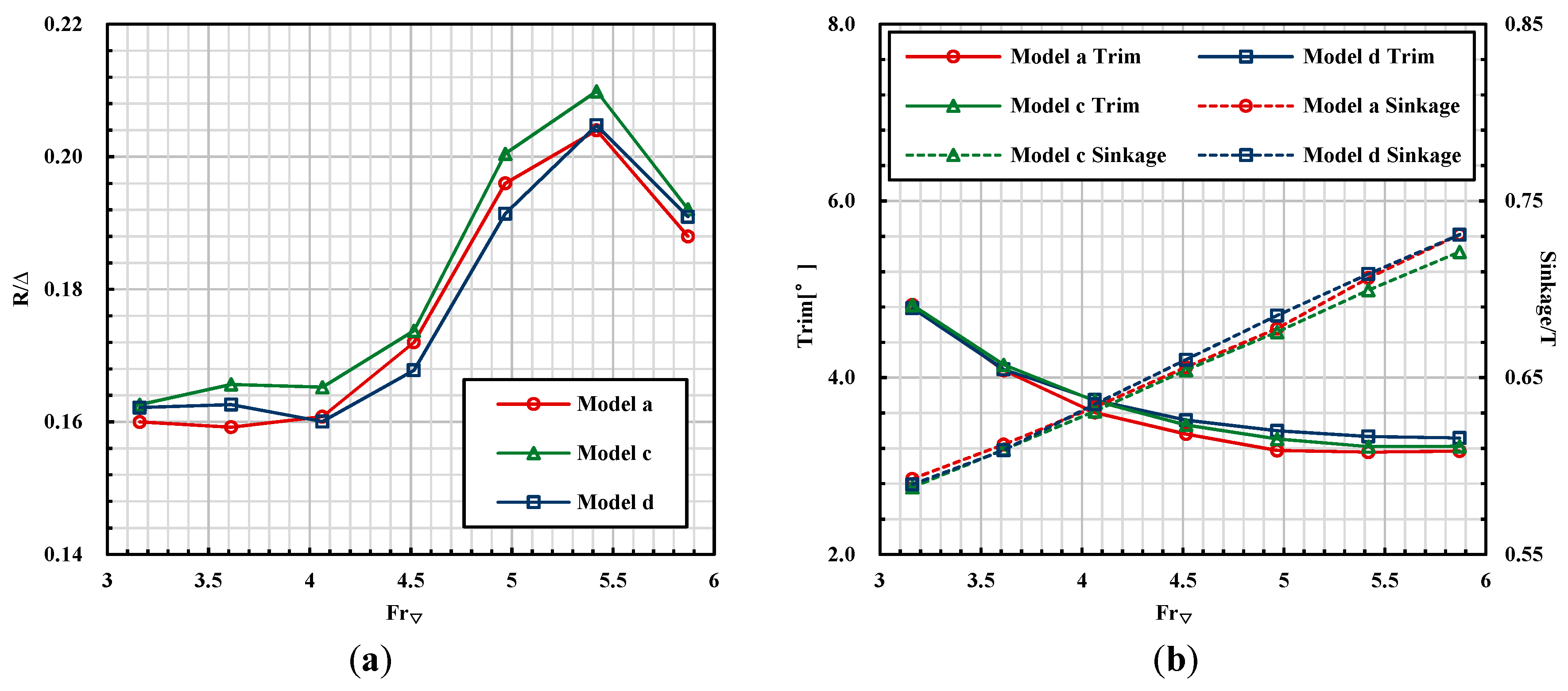
Using the aforementioned numerical tools, the modified models are investigated. The calculated resistance and trim angle versus the Froude number are summarized in Figure 14. It can be found that changing the camber of air intake affects hull behaviour slightly, while the influence on resistance is obvious. The drag is increased at the calculated speeds when the camber is shortened, while enlarging the camber could reduce drag at the Froude numbers ranging from 4.06 to 4.97, the maximum drag reduction is 2.5%. Generally, compared with the original model, modifying camber could make the resistance vary from −3% (decrease resistance) to 4% (increase resistance).
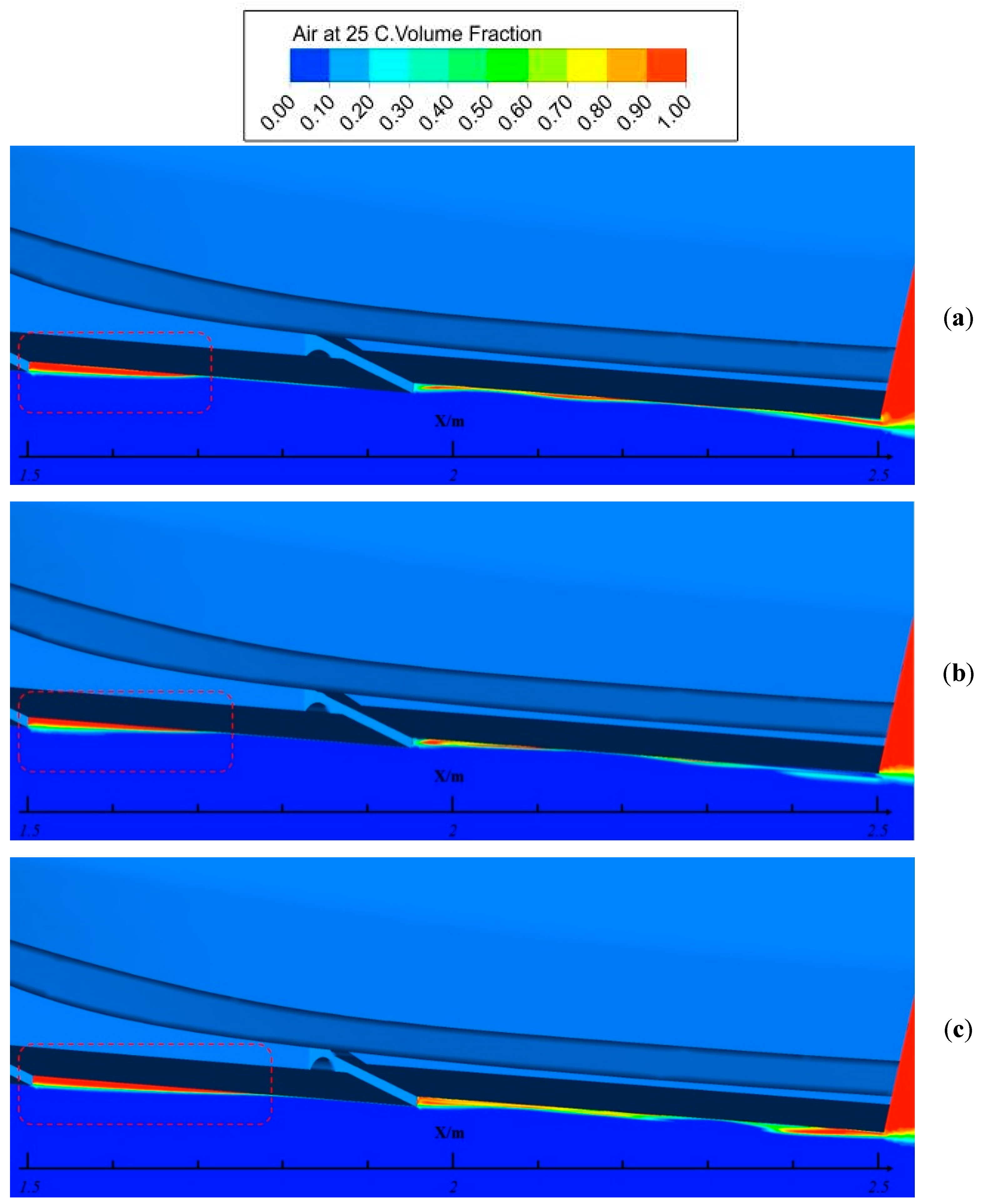
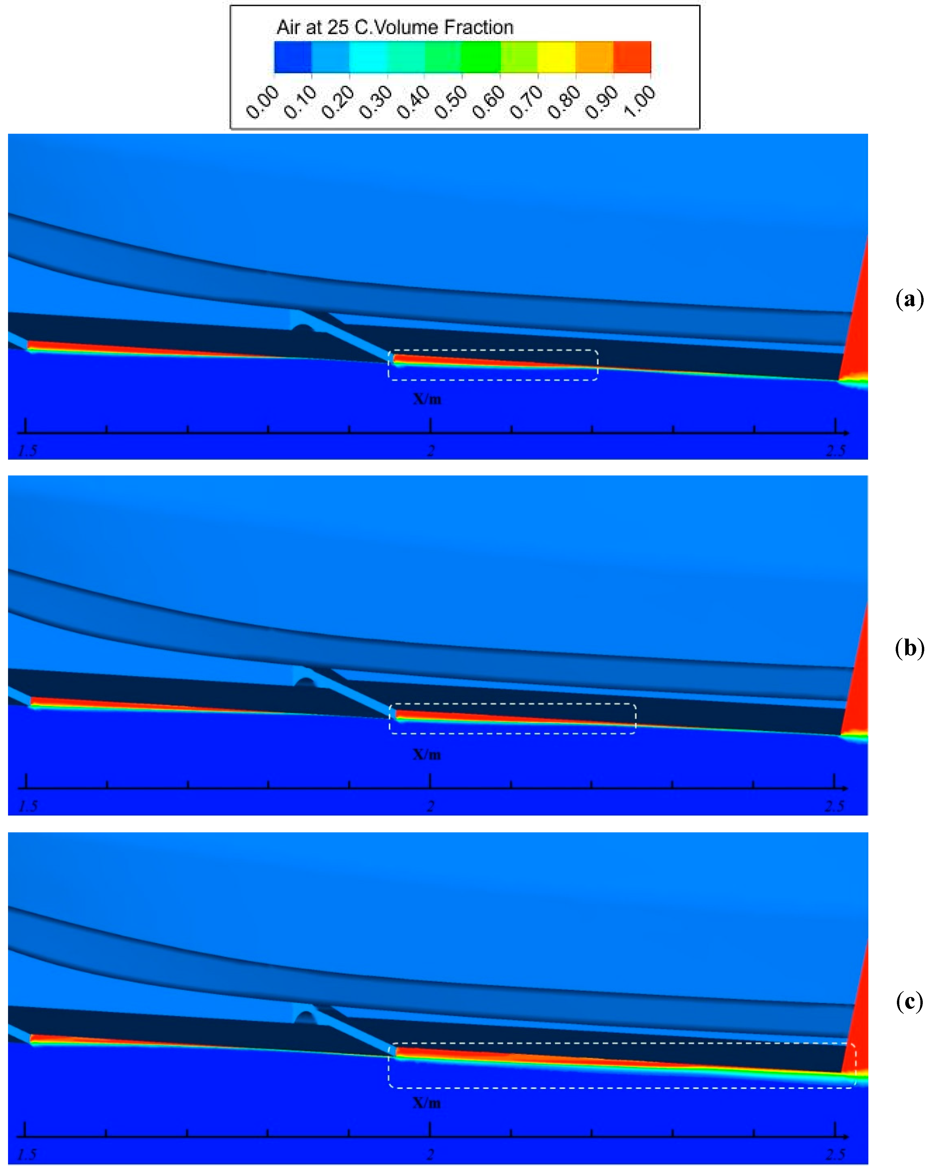
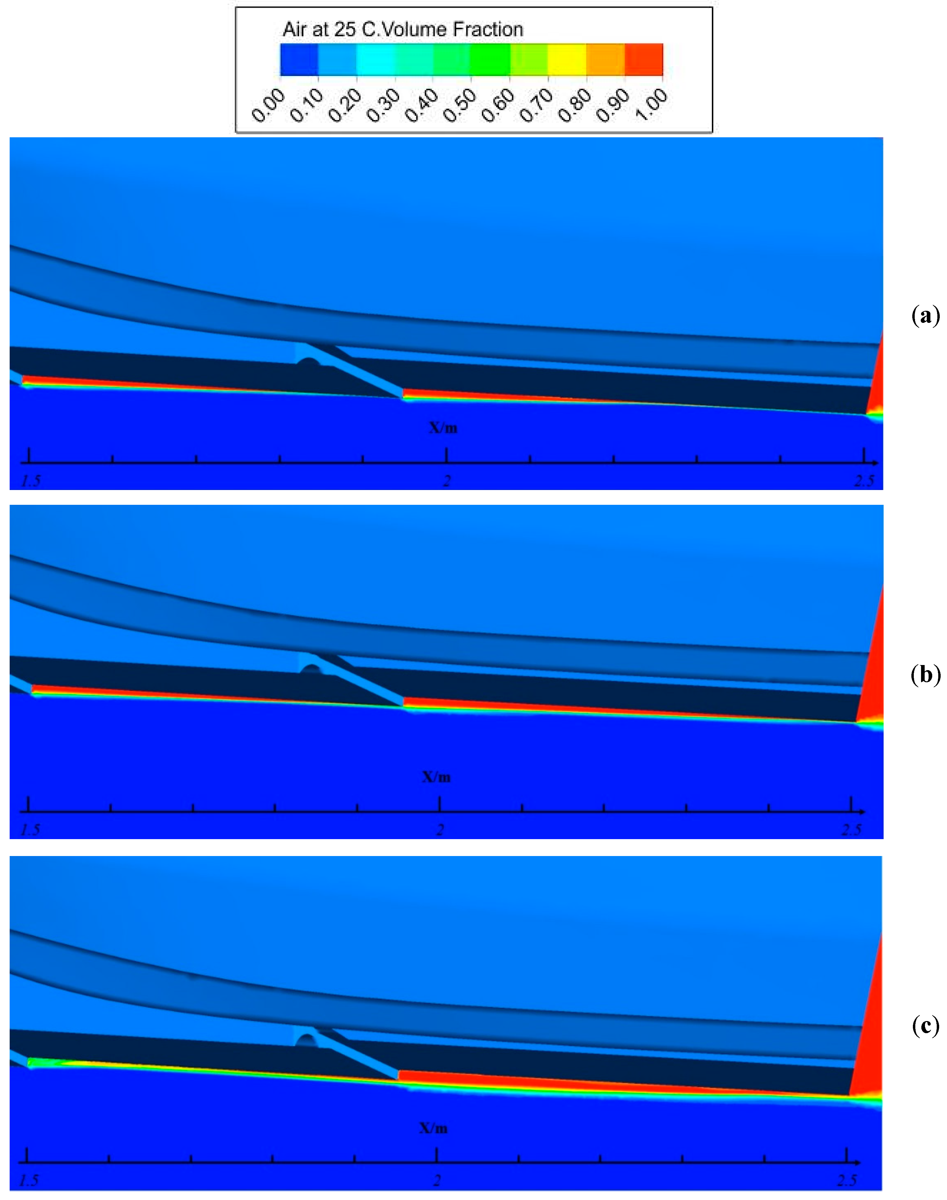
In Figure 15, Figure 16 and Figure 17, the air volume fraction in the centre plane of original and modified models at Froude numbers of 3.16, 4.52 and 5.87 are compared to present the influence of air intake camber on the air cavity form.
As the Figure 15 shown, the speed during Froude number of 3.16 is the beginning of the planing, the air cavity is concentrated behind the first step. The model c has the thickest air cavity compared with others.
With the increase of the speed, at Froude number of 4.52, the model d created the most massive air cavity as the Figure 16 shown, however, it can be seen that the air cavity behind the first step is much less than others.
In Figure 17, the model d has an obvious and stout air cavity behind the second step but the nearly disappeared air cavity behind the first step that caused the drag increased. Among the other models, the model a has a better performance.
It can be seen that the air cavity of model d is slightly smaller than that of model c at the Froude number of 3.16. However, with the higher growth rate, its longitudinal dimension could overtake model c at the following speed. Therefore, changing air intake camber affects not only the size of the air cavity but also the growth rate. That is, increasing the camber, in some degree, is beneficial to extending the air cavity but a negative influence will be caused by excessive enlargement.
5. Conclusion
In this study, several planing trimaran models with different configurations have been investigated via numerical methods. Generally, the work presented here belongs to the field of CFD incremental research. The focus is on the working mechanism of air intake and its influence. Based on analysis of the calculated result, the following conclusions can be drawn:
- The numerical method used here is credible for the simulation of a high-speed planing boat. The advantage is mainly reflected in the modelling of hull motion, which is implemented by the coupling iterative solving of the governing and motion equations. Therefore, it is not necessary to estimate the hull position before solving flow field and the dependence on experimental data is weakened.
- Air intake could evidently decrease the resistance when the Froude number is above 4.97, indicating that this drag-reducing measurement is applicable for a high-speed stepped planing craft such as the planing trimaran. The drag-reducing effect of air intake depends mainly on its cambered configuration. Compared with the model without air intake, the air flow in front of the hull body can easily be sucked into the air cavity, which could further decrease the wetted area and frictional resistance.
- Numerical results of models with various cambers show that shortening the camber has a negative influence on resistance and air cavity, while enlarging the camber could improve resistance performance at Froude numbers between 4.06 and 4.97 but the air cavity would get smaller. Therefore, in terms of the particular geometry of planing trimaran, the original air intake configuration possesses the best overall resistance performance and the design of air intake should be carefully considered.
Author Contributions
L.D. and Y.J. designed the framework of the study, conducted fieldwork and analyzed data, writing; project administration and funding acquisition, H.S.; supervision, P.L.; All authors discussed the results and commented on the manuscript.
Funding
This research was funded by Funds for Key Laboratory, grant number 614222303030917, Fundamental Research Funds for Central Universities, grant number HEUCF180101 and Special funding for high-tech ships, grant number 2016(026).
Acknowledgments
Thanks for the General Institute of ship and Offshore platform Technology, Harbin Engineering University.
Conflicts of Interest
The authors declare no conflict of interest.
References
- Jiang, Y.; Sun, H.B.; Zou, J.; Hu, A.K.; Yang, J.L. Analysis of tunnel hydrodynamic characteristics for planing trimaran by model tests and numerical simulations. Ocean Eng. 2016, 113, 101–110. [Google Scholar] [CrossRef]
- Lee, E.; Pavkov, M.; Mccueweil, L. The Systematic Variation of Step Configuration and Displacement for a Double-step Planing Craft. J. Ship Prod. Des. 2014, 30, 89–97. [Google Scholar] [CrossRef]
- Taunton, D.J.; Hudson, D.A.; Shenoi, R.A. Characteristics of a series of high speed hard chine planing hulls-Part 1: Performance in calm water. Int. J. Small Craft Technol. 2010, 153, B1–B22. [Google Scholar]
- Taunton, D.J.; Hudson, D.A.; Shenoi, R.A. Characteristics of a series of high speed hard chine planing hulls-Part II: Performance in waves. Int. J. Small Craft Technol. 2011, 152, 55–75. [Google Scholar]
- Yousefi, R.; Shifaghat, R.; Shakeri, M. Hydrodynamic analysis techniques for high-speed planing hulls. Appl. Ocean Res. 2013, 42, 105–113. [Google Scholar] [CrossRef]
- Lotfi, P.; Ashrafizaadeh, M.; Esfahan, R.K. Numerical investigation of a stepped planing hull in calm water. Ocean Eng. 2015, 94, 103–110. [Google Scholar] [CrossRef]
- Veysi, S.T.G.; Bakhtiari, M.; Ghassemi, H. Toward numerical modeling of the stepped and non-stepped planing hull. J. Braz. Soc. Mech. Sci. 2015, 37, 1635–1645. [Google Scholar] [CrossRef]
- Bakhtiari, M.; Veysi, S.; Ghassemi, H. Numerical Modeling of the Stepped Planing Hull in Calm Water. Int. J. Eng. Trans. B Appl. 2016, 29, 236–245. [Google Scholar]
- Azcueta, R.; Rousselon, N. CFD Applied to Super and Mega Yacht Design. In Proceedings of the Design, Construction and Operation of Super and Mega Yachts Conference, Genova, Italy, 15 April 2009. [Google Scholar]
- Sheingart, Z. Hydrodynamics of High Speed Planing Hulls with Partially Ventilated Bottom and Hydrofoils. Master’s Thesis, Massachusetts Institute of Technology, Cambridge, MA, USA, 2014. [Google Scholar]
- Faison, L.A. Design of a High Speed Planing Hull with a Cambered Step and Surface Piercing Hydrofoils. Master’s Thesis, Massachusetts Institute of Technology, Cambridge, MA, USA, 2014. [Google Scholar]
- De Marco, A.; Mancini, S.; Miranda, S.; Scognamiglio, R.; Vitiello, L. Experimental and numerical hydrodynamic analysis of a stepped planing hull. Appl. Ocean Res. 2017, 64, 135–154. [Google Scholar]
- Ghassabzadeh, M.; Ghassemi, H. An innovative method for parametric design of planing tunnel vessel. Ocean Eng. 2013, 60, 14–27. [Google Scholar] [CrossRef]
- Yousefi, R.; Shfaghat, R.; Shakeri, M. High-speed hull drag reduction using tunnel. Ocean Eng. 2014, 84, 54–60. [Google Scholar] [CrossRef]
- Moghadam, H.K.; Shafaghat, R.; Yousefi, R. Numerical investigation of the tunnel aperture on drag reduction in a high-speed tunneled planing hull. J. Braz. Soc. Mech. Sci. Eng. 2015, 37, 1719–1731. [Google Scholar]
- Maronnier, V.; Picasso, M.; Rappaz, J. Numerical simulation of free surface flows. J. Comput. Phys. 1999, 155, 439–455. [Google Scholar] [CrossRef]
Figure 1.
Trimaran planing boat model and air duct.

Figure 2.
Computational process.

Figure 3.
Calculation domain.

Figure 4.
Mesh generation.

Figure 5.
Calculated resistance in mesh independence analysis.

Figure 6.
Test plan.

Figure 7.
Comparisons of numerical result and experimental data: (a) Resistance; (b) Trim angle and sinkage.
Figure 7.
Comparisons of numerical result and experimental data: (a) Resistance; (b) Trim angle and sinkage.

Figure 8.
Cross-section comparison of models a and b.

Figure 9.
Computational resistance and hull behaviour of models a and b: (a) Resistance; (b) Trim angle and sinkage.
Figure 9.
Computational resistance and hull behaviour of models a and b: (a) Resistance; (b) Trim angle and sinkage.

Figure 10.
Streamline distribution at bilge: (a) Model a; (b) Model b.

Figure 11.
Drag-reducing mechanism of air duct: (a) with air intake; (b) without air intake.

Figure 12.
Comparison of air cavity: (a) Model a; (b) Model b.

Figure 13.
Cross-section comparison of models a, c and d.

Figure 14.
Computational resistance and hull behaviours of models a, c and d: (a) Resistance; (b) Trim angle and sinkage.
Figure 14.
Computational resistance and hull behaviours of models a, c and d: (a) Resistance; (b) Trim angle and sinkage.

Figure 15.
Air cavity comparison at speed of Fr = 3.16: (a) Model c; (b) Model a; (c) Model d.

Figure 16.
Air cavity comparison at speed of Fr = 4.52: (a) Model c; (b) Model a; (c) Model d.

Figure 17.
Air cavity comparison at speed of Fr=5.42: (a) Model c; (b) Model a; (c) Model d.


Table 1.
Main dimensions of ship model.
| Main Dimension | Symbol | Value |
|---|---|---|
| Overall Length (m) | 2.5 | |
| Main hull beam (m) | B | 0.46 |
| Tunnel beam (m) | b | 0.125 |
| Tunnel height (m) | h | 0.175 |
| Longitudinal centre of gravity (m) | LCG | 0.75 |
| Displacement (kg) | Δ | 130 |
| Draft (m) | T | 0.17 |
| Deadrise angle (°) | β | 13 |
| Longitudinal location of 1st step (m) | L1 | 1 |
| Longitudinal location of 2nd step (m) | L2 | 0.55 |
| Step height (m) | H | 0.012 |
| Air intake camber (m) | f | 0.012 |
Table 2.
Computational result and experimental data.
| Fr | R/Δ | Trim (deg) | Sinkage/T | ||||||
|---|---|---|---|---|---|---|---|---|---|
| Cpmt. | Exp. | Err. (%) | Cpmt. | Exp. | Err. (%) | Cpmt. | Exp. | Err. (%) | |
| 3.16 | 0.160 | 0.165 | 2.99 | 4.82 | 5.75 | 16.09 | 0.593 | 0.634 | 6.51 |
| 3.61 | 0.159 | 0.164 | 2.88 | 4.08 | 4.85 | 15.81 | 0.612 | 0.637 | 3.88 |
| 4.06 | 0.161 | 0.170 | 5.28 | 3.61 | 4.06 | 11.17 | 0.633 | 0.648 | 2.20 |
| 4.52 | 0.172 | 0.183 | 6.13 | 3.36 | 3.65 | 7.88 | 0.656 | 0.663 | 1.13 |
| 4.97 | 0.196 | 0.209 | 6.01 | 3.18 | 3.38 | 6.01 | 0.678 | 0.662 | −2.43 |
| 5.42 | 0.204 | 0.231 | 11.78 | 3.16 | 3.52 | 10.28 | 0.707 | 0.680 | −3.83 |
| 5.87 | 0.188 | 0.220 | 14.66 | 3.17 | 3.69 | 14.10 | 0.731 | 0.709 | −3.07 |
© 2019 by the authors. Licensee MDPI, Basel, Switzerland. This article is an open access article distributed under the terms and conditions of the Creative Commons Attribution (CC BY) license (http://creativecommons.org/licenses/by/4.0/).
Share and Cite
MDPI and ACS Style
Du, L.; Sun, H.; Jiang, Y.; Li, P. Numerical Research on the Resistance Reduction of Air Intake. Water 2019, 11, 280. https://doi.org/10.3390/w11020280
AMA Style
Du L, Sun H, Jiang Y, Li P. Numerical Research on the Resistance Reduction of Air Intake. Water. 2019; 11(2):280. https://doi.org/10.3390/w11020280
Chicago/Turabian StyleDu, Lei, Hanbing Sun, Yi Jiang, and Ping Li. 2019. "Numerical Research on the Resistance Reduction of Air Intake" Water 11, no. 2: 280. https://doi.org/10.3390/w11020280
Note that from the first issue of 2016, this journal uses article numbers instead of page numbers. See further details here.