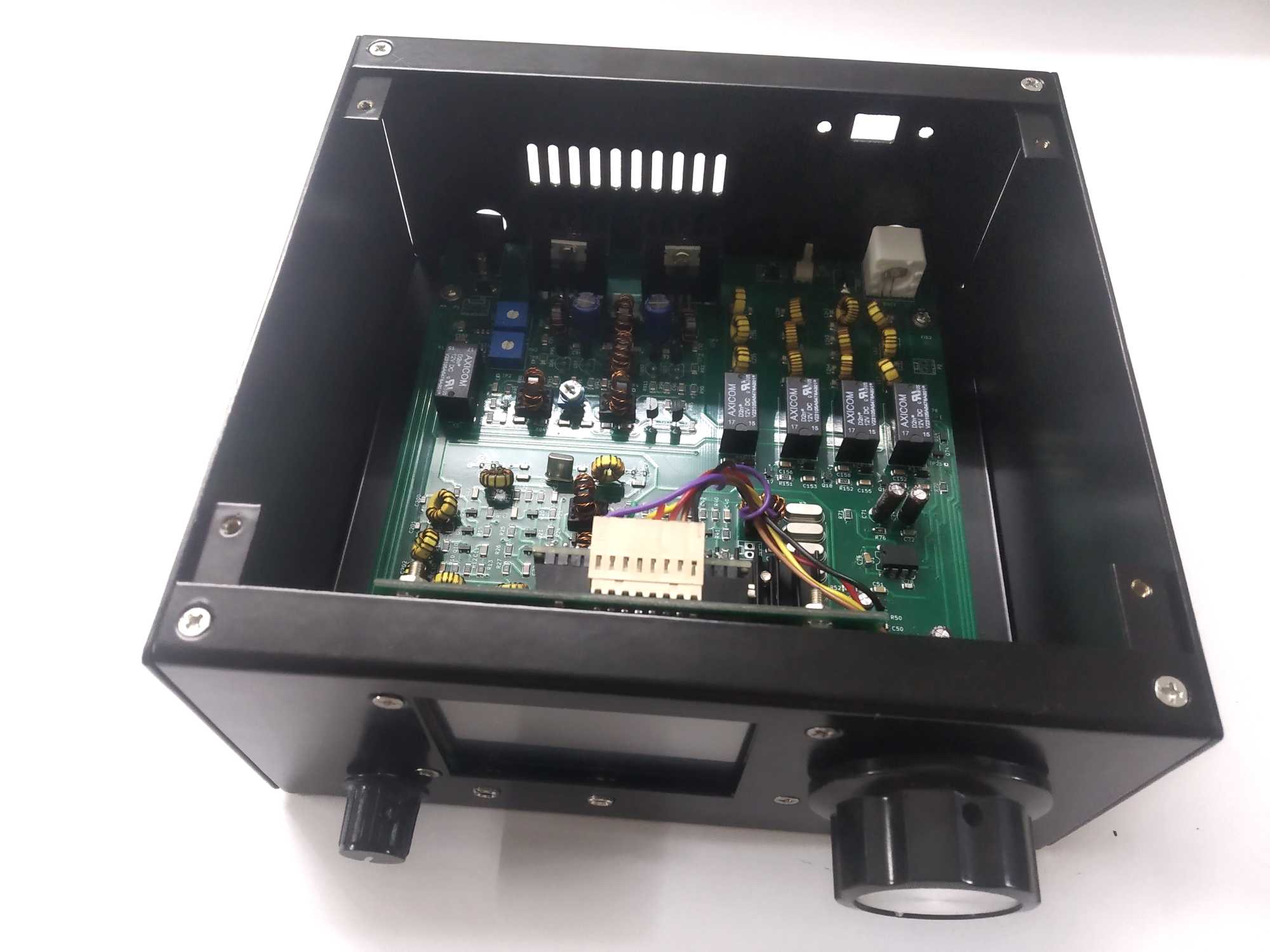
Step 1
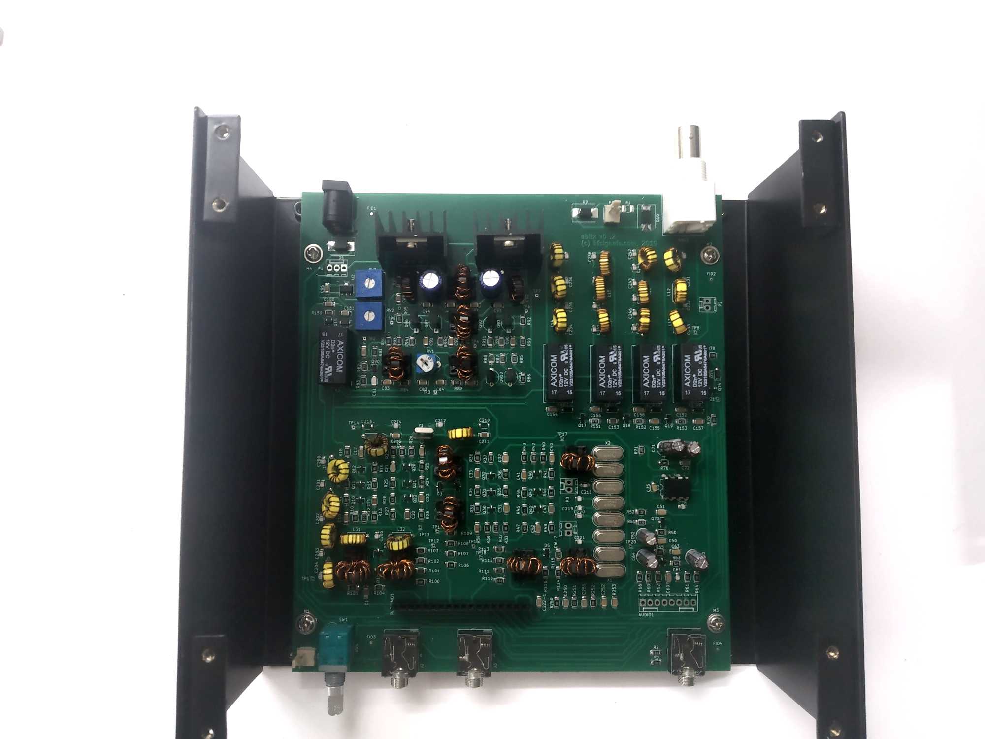
Afix the main board to the chassis with the four round headed M3 screws. IMPORTANT: Orient the board such that the volume control knob sticks out of the board.
Step 2:
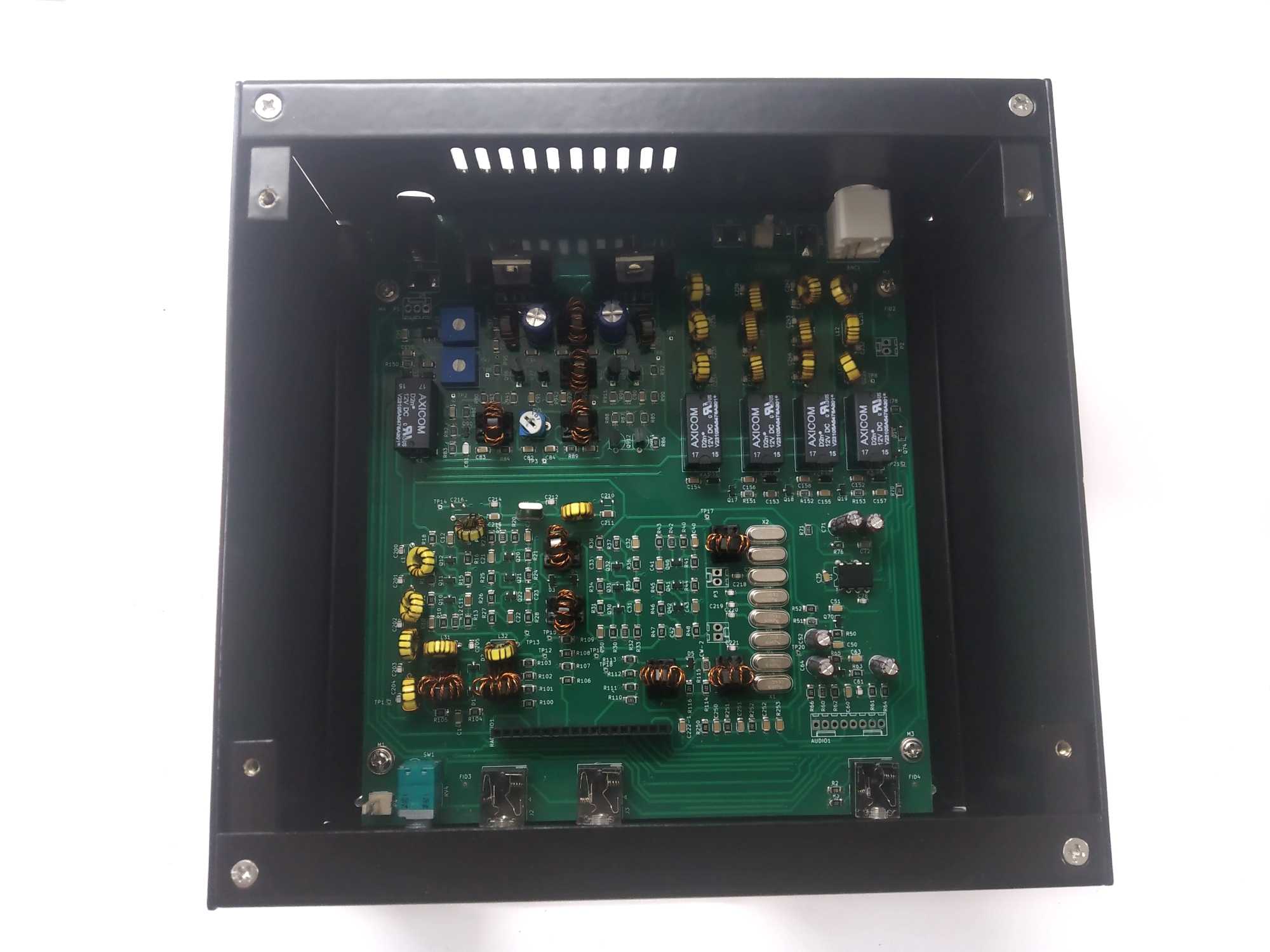 Attach the front and back panels with four screws each. Check that all the connectors are properly inserted through the panels.
Step 3
Install the tuning encoder with its pre-soldered connector
Step 4
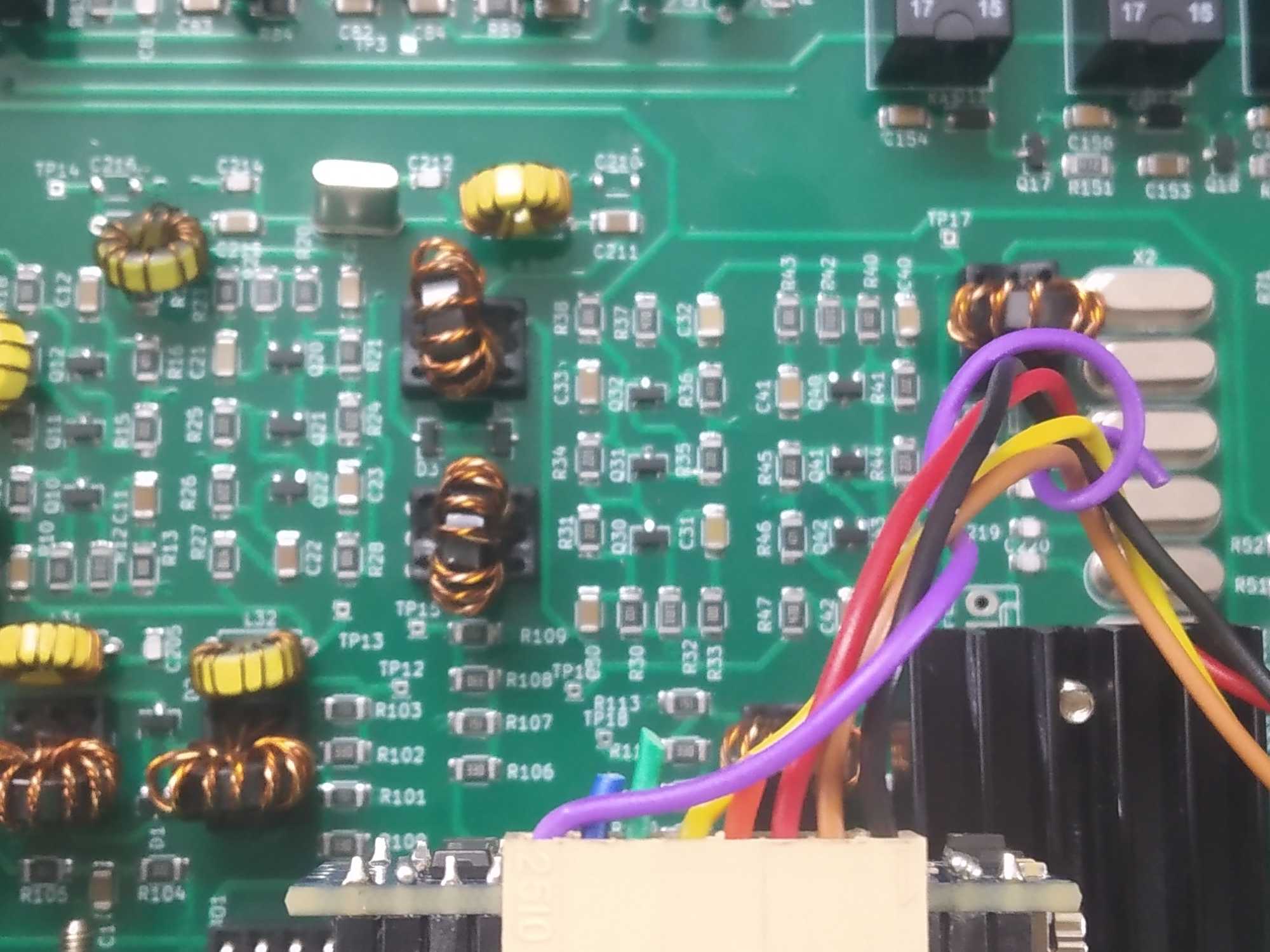
Carefully insert the TFT Raduino (Display) card into the Main board. Check that all the 18 pins are properly seated. Plug-in the Tuning Encoder connector’s wires to the top connector of the TFT Raduino (Display) card.
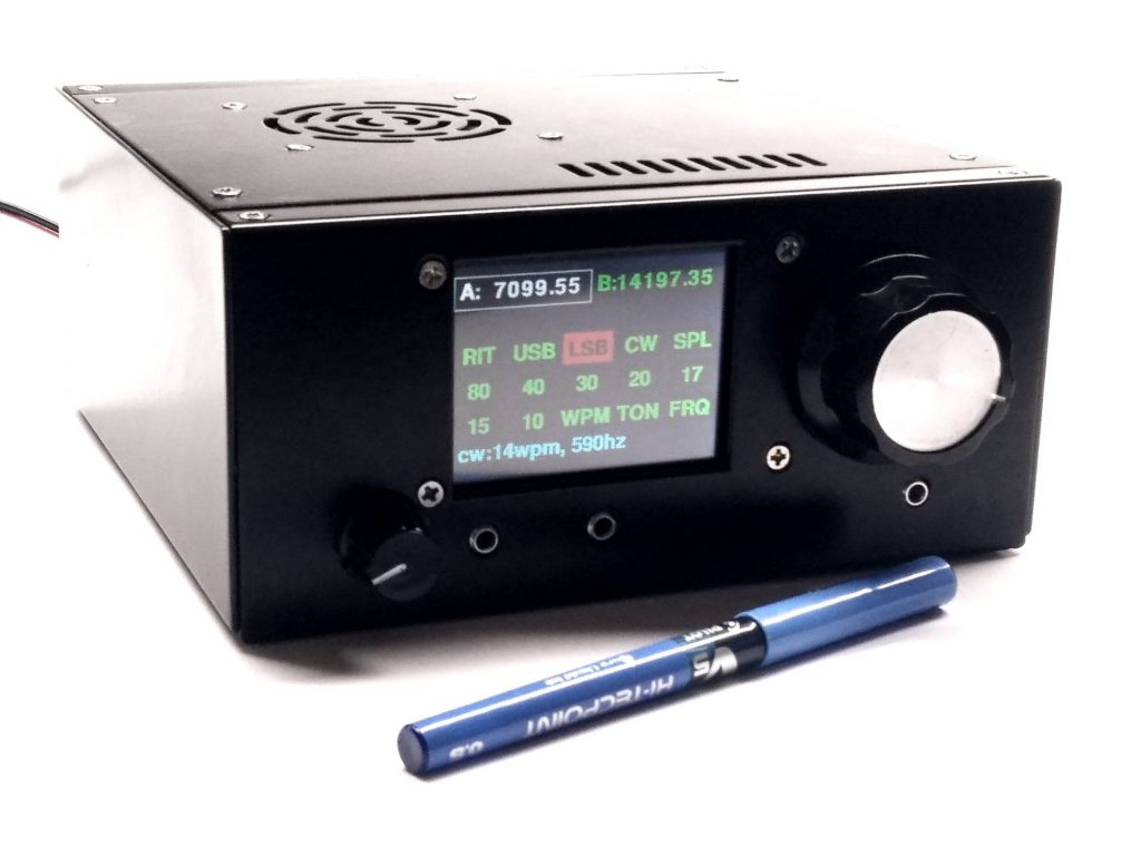
Step 5
Attach the knobs to the Tuning Encoder and the volume control. Use a small srewdriver to tighten the mounting screws on the side of the knobs for proper grip on the the spindles.
Using 4 of flat head, 6 mm, M3 screws, attach the Display board (The TFT Raduino) to the front -panel.
Step 6
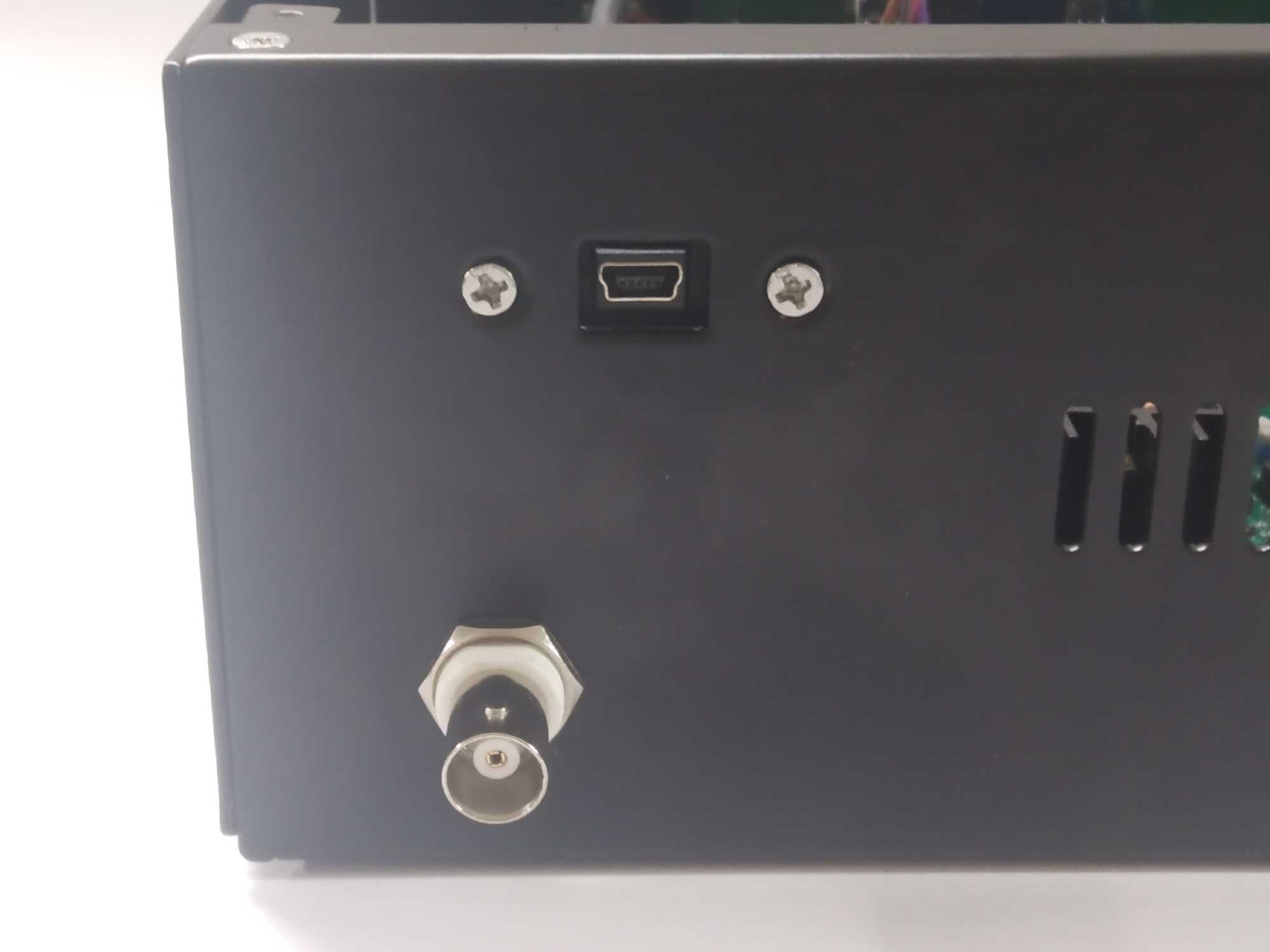
Using two flat head, M3 screws (10 mm) fasten the USB extender cable to the back panel. Tighten the large nut around the BNC socket.
Step 7
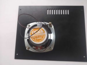
Fasten the speaker to the grill with four M3 flat head screws and nuts
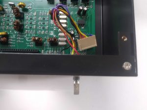
Step 8
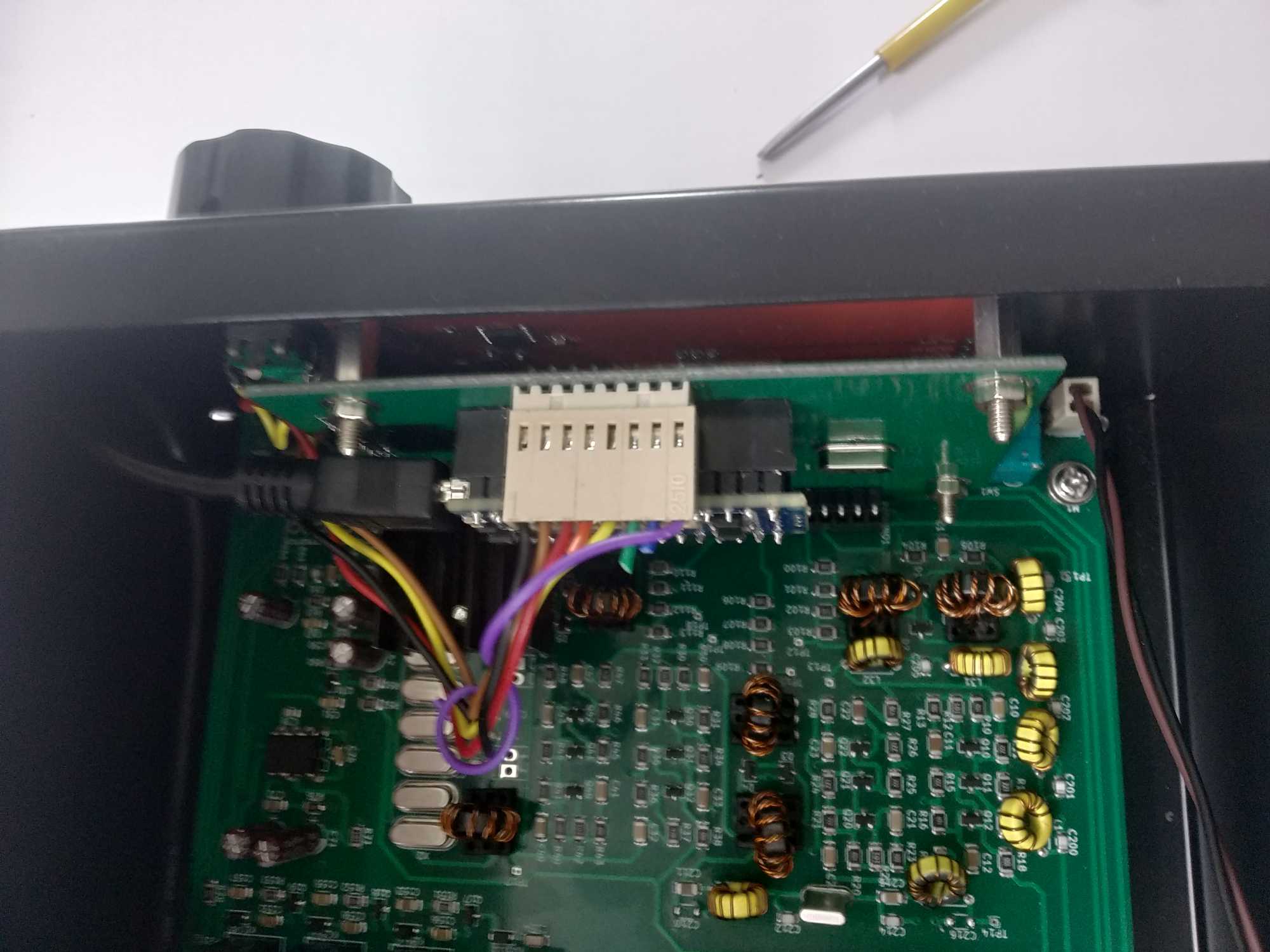
Attach the USB extender to the Arduino Nano on the back of the TFT Raduino board.
Attach the speaker cable to the connector next to the volume control.
Step 9
 Screw in the top panel with four of M3, 10 mm screws and switch on your new uBITX transceiver!
Next, Learn to operate your uBITX !