Influence of Convex and Concave Curvatures in a Coastal Dike Line on Wave Run-up

 , , , ,
  and
and 
Abstract
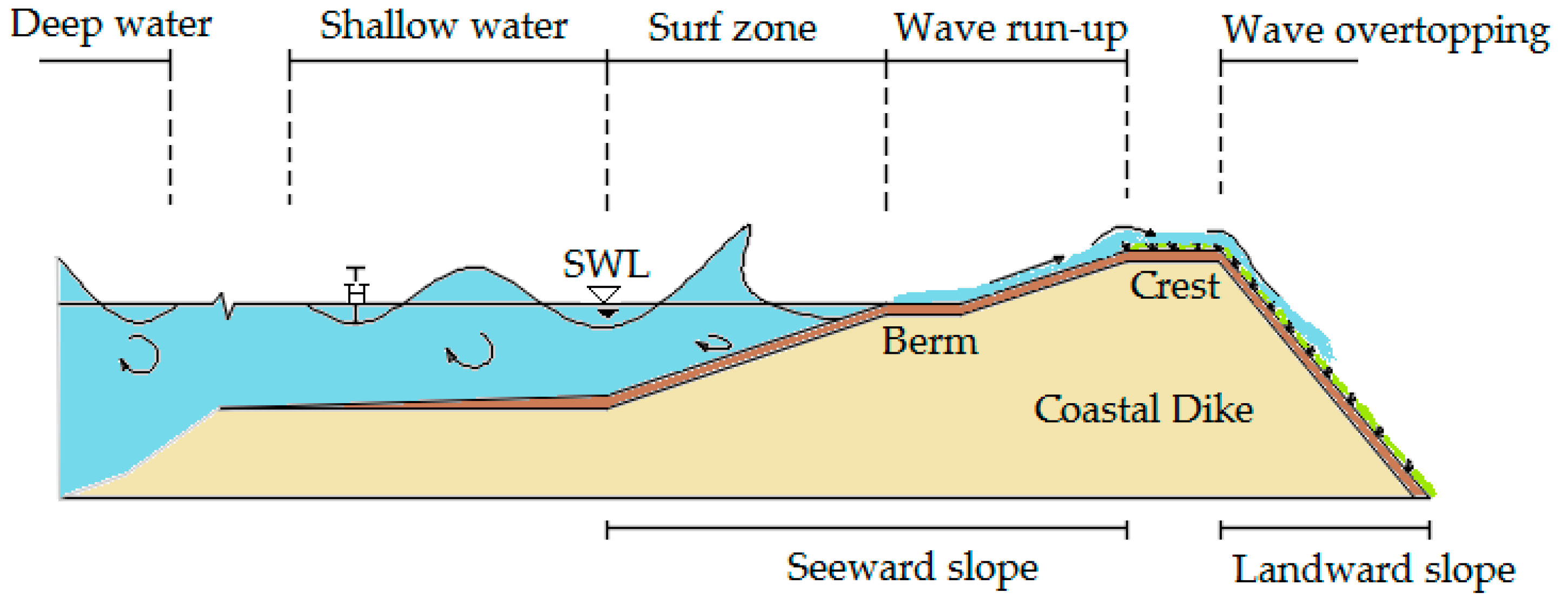
:1. Introduction
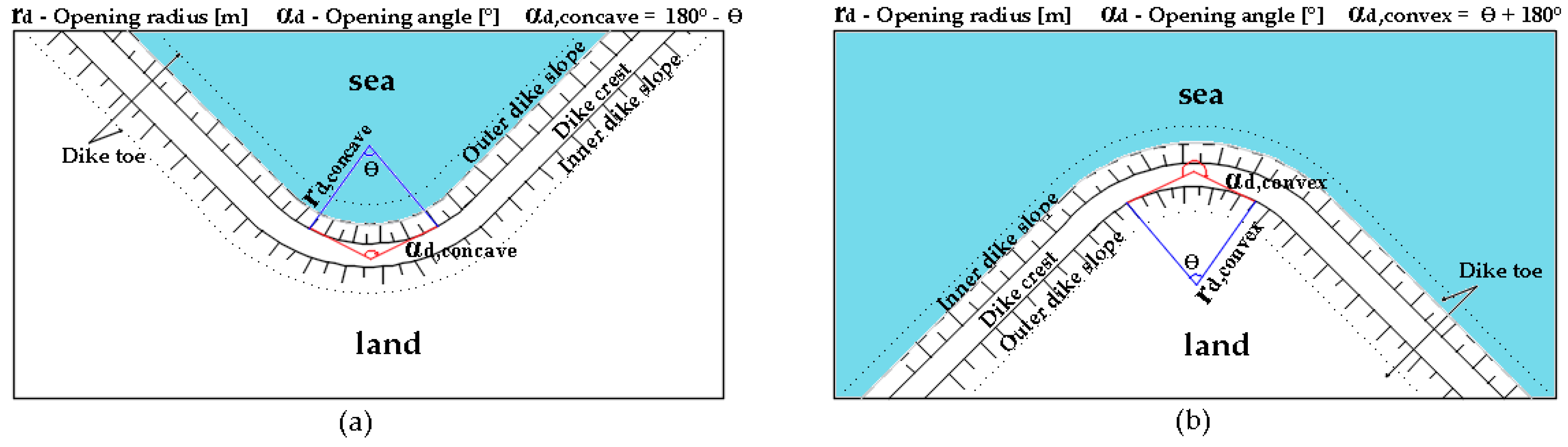
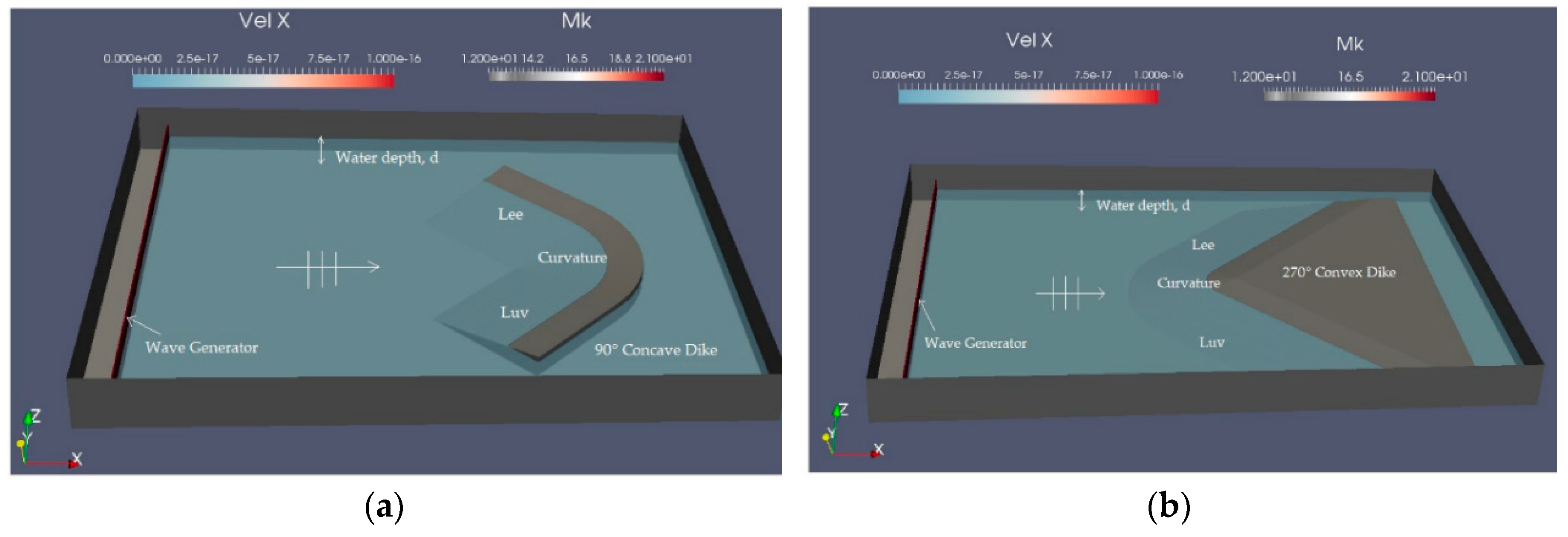
1.1. Influence of a Curvature in a Dike Line
1.2. Literature Review
2. Numerical Model
2.1. DualSPHysics
2.2. OpenFOAM
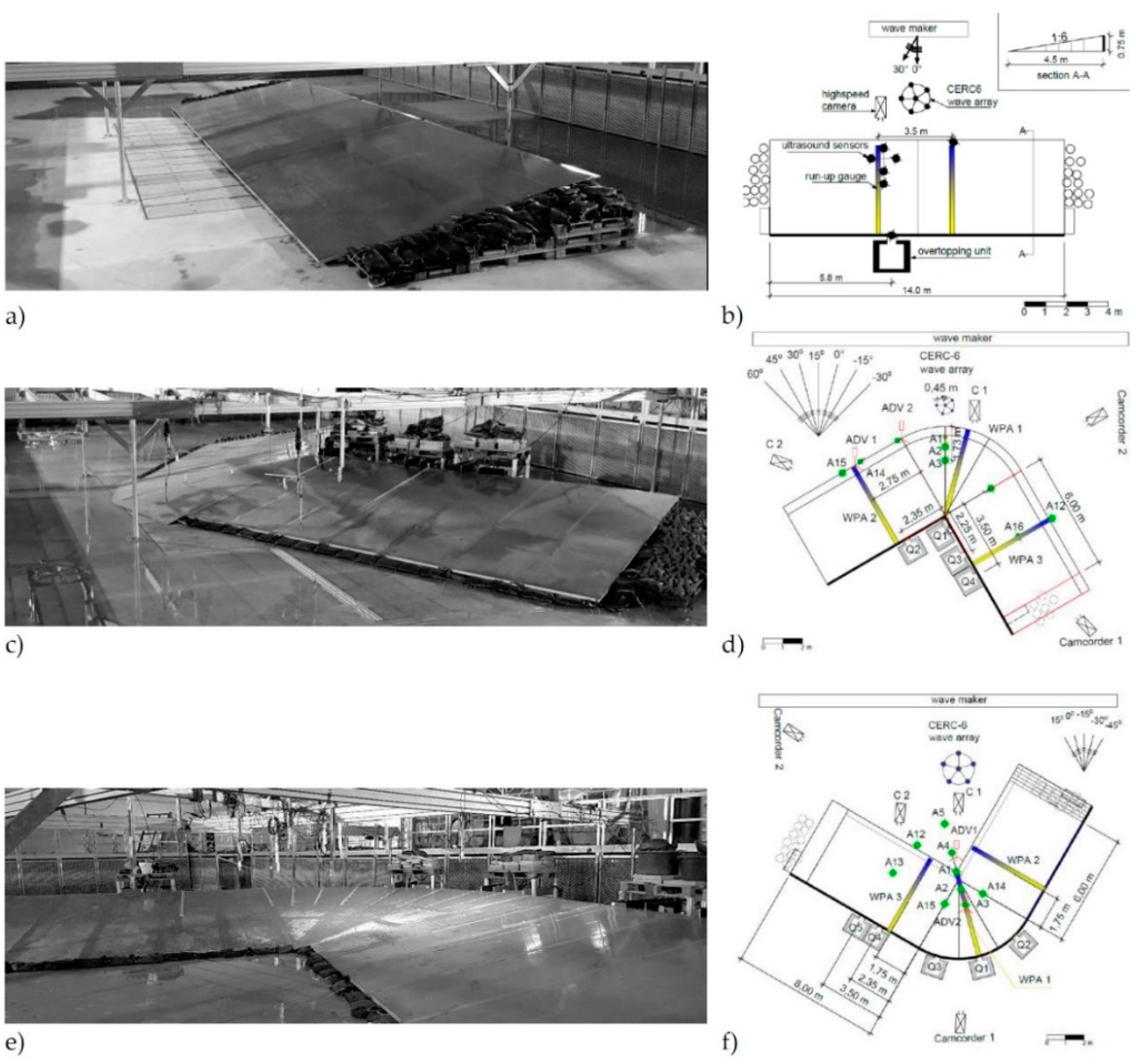
3. Physical Model
4. Numerical Investigation on a Curved Dike Line
4.1. Calibration Study
4.2. Numerical Model Set-Up
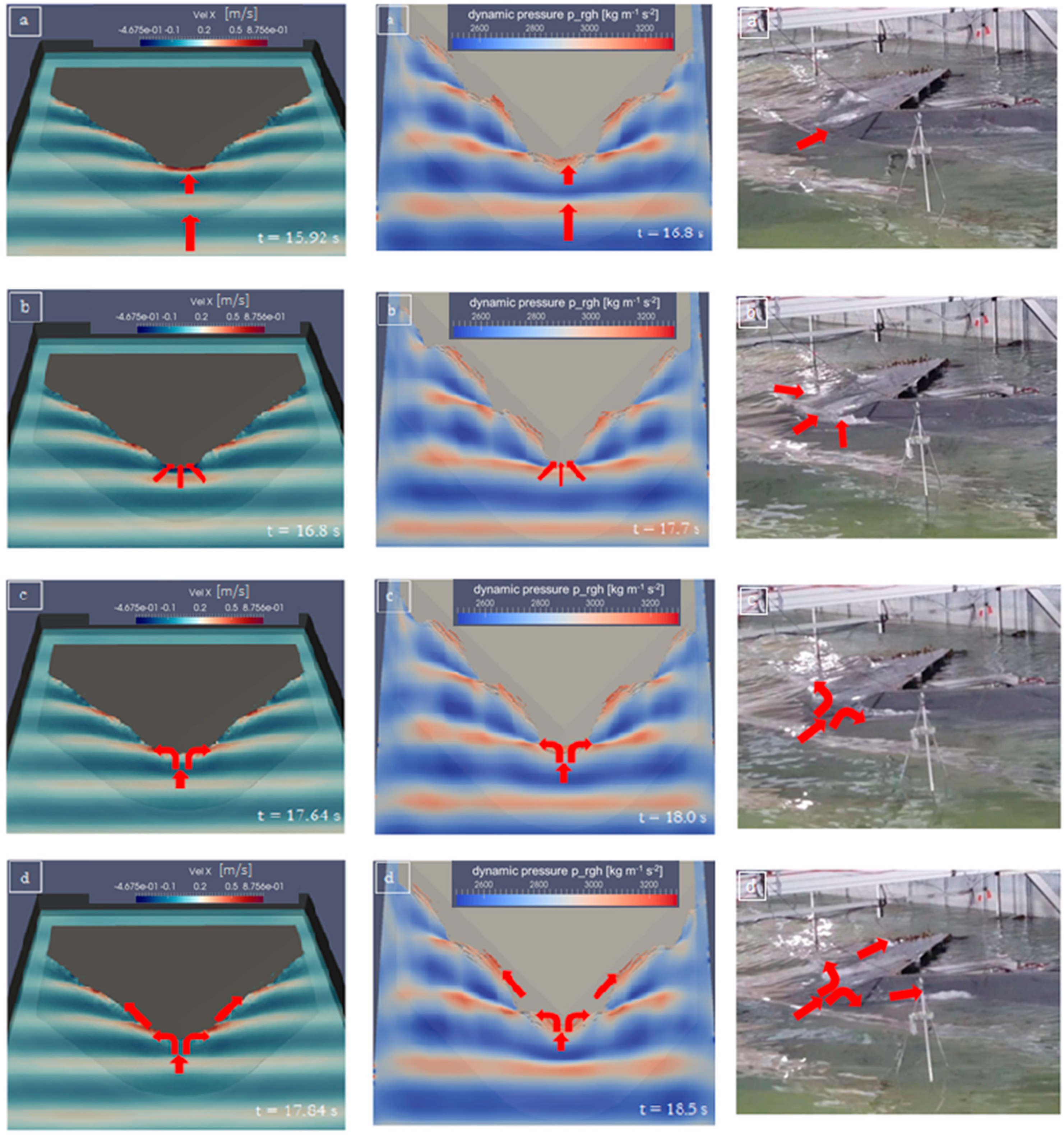
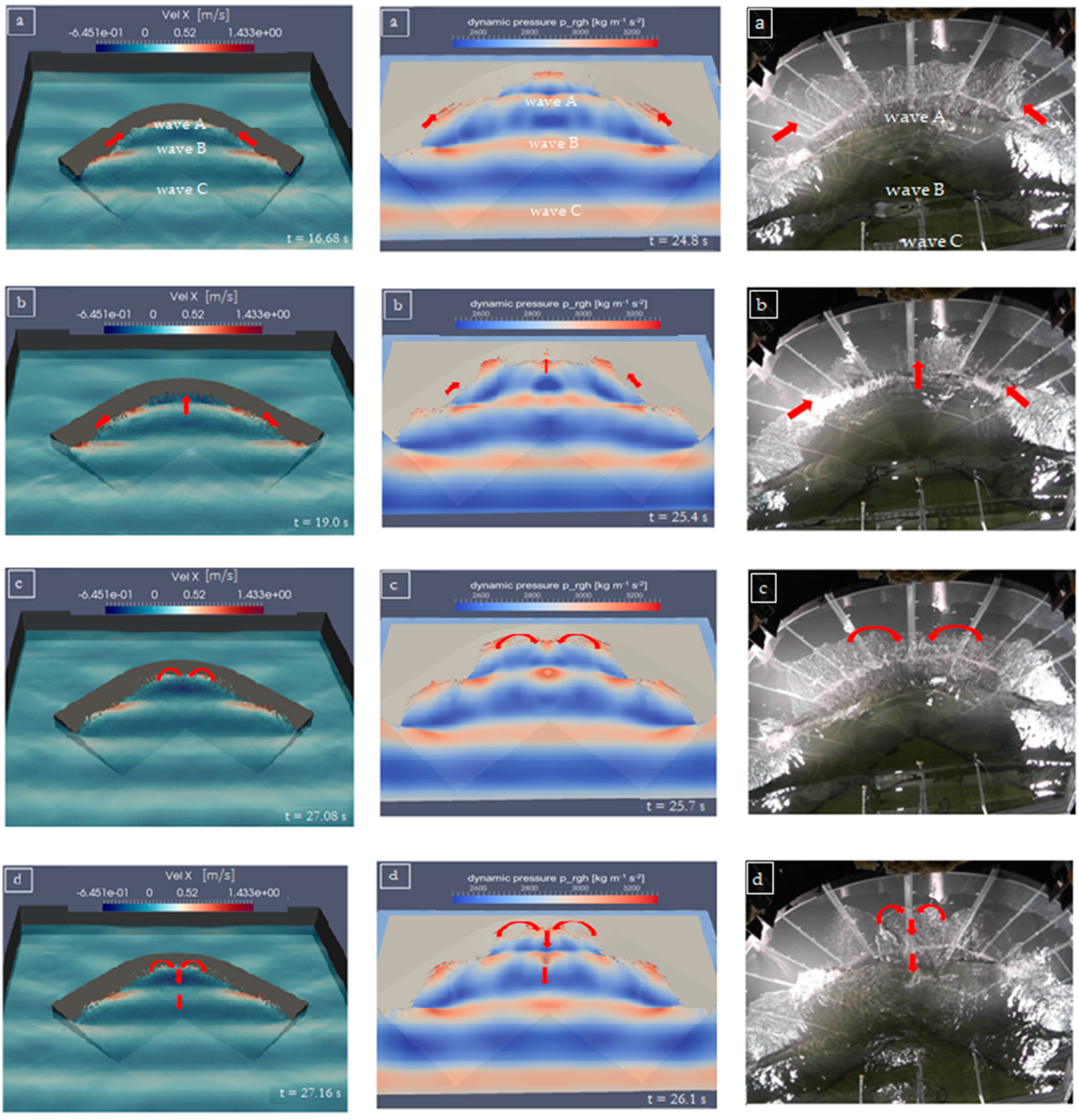
4.3. Transformation Processes on a Curved Dike
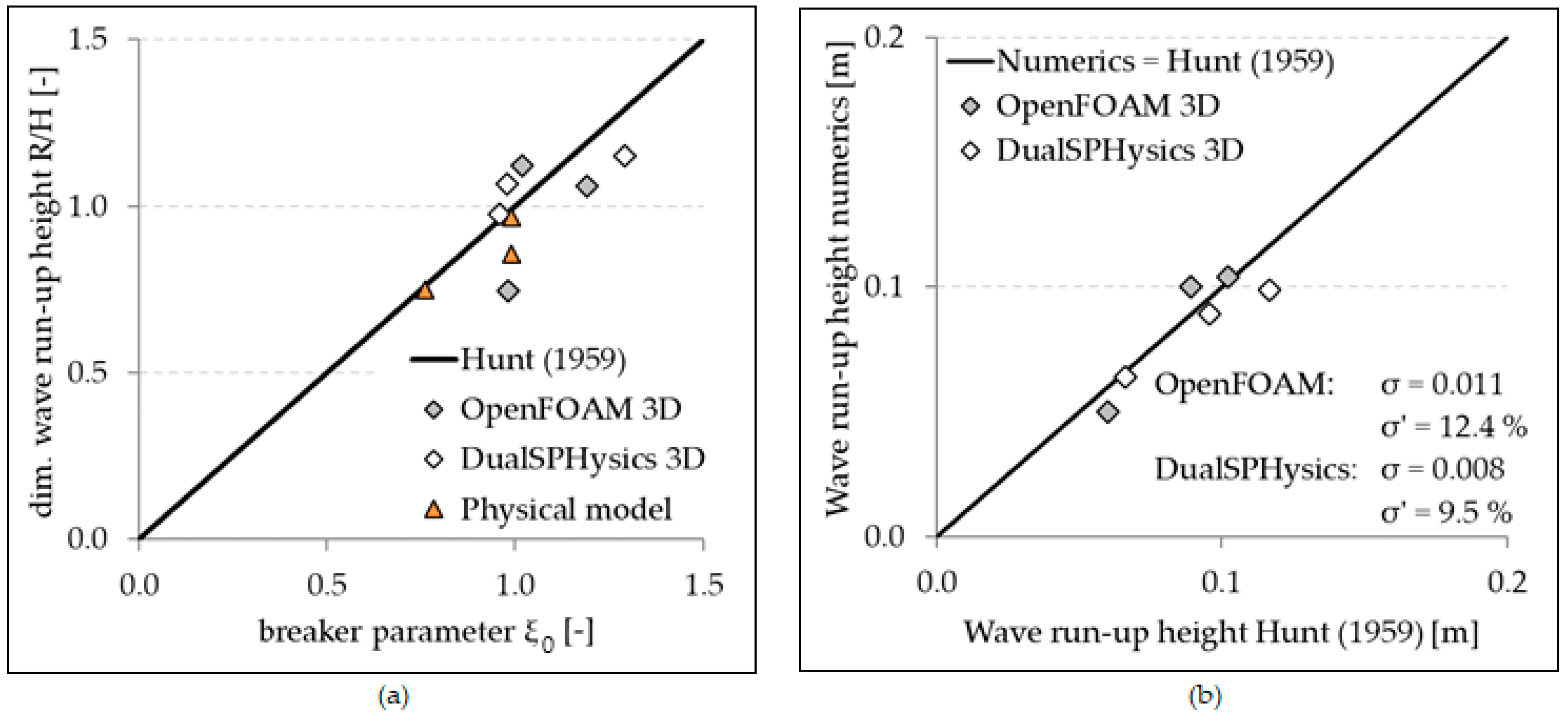
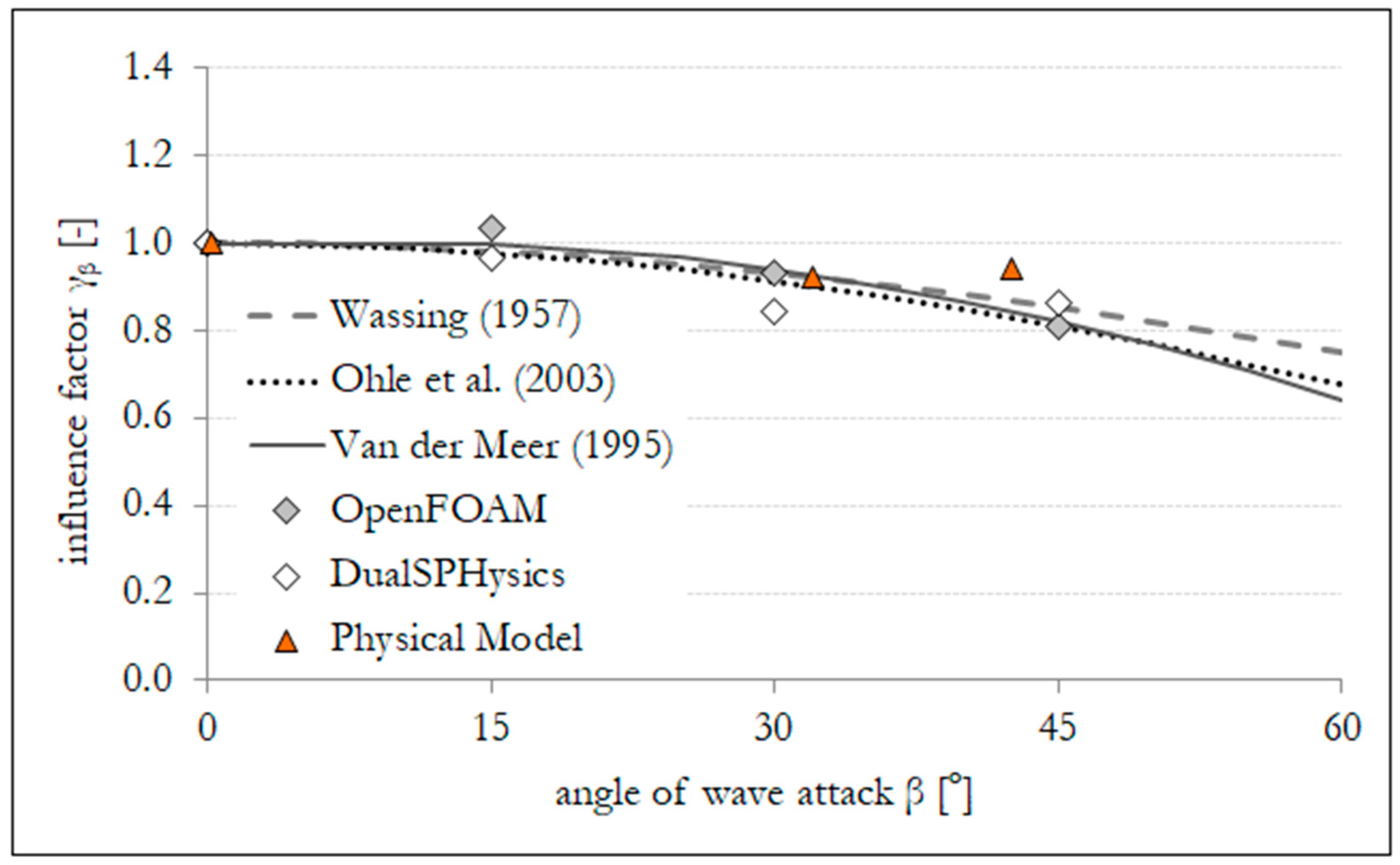
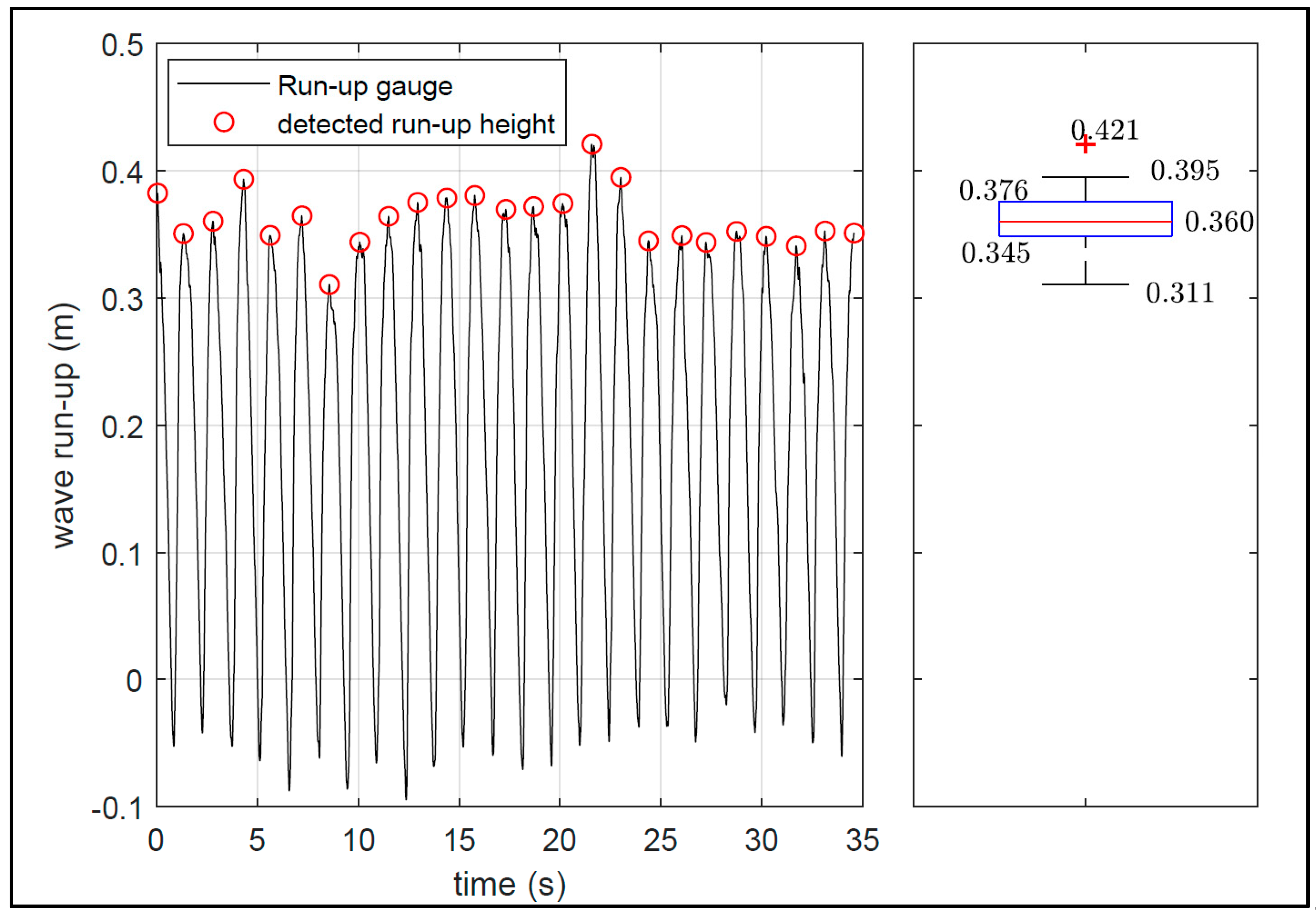
5. Analysis Approach
6. Results and Discussion
7. Conclusions and Future Outlook
Author Contributions
Funding
Conflicts of Interest
Appendix A

References
- EurOtop. Manual on Wave Overtopping of Sea Defences and Related Structures: An Overtopping Manual Largely Based on European Research, but for Worldwide Application; EurOtop: Brussels, Belgium, 2018. [Google Scholar]
- Mayer, R.H.; Kriebel, D.L. Wave run-up on composite slopes and concave beaches. In Proceedings of the 24th Coastal Engineering Conference, Kobe, Japan, 23–28 October 1994; pp. 2325–2339. [Google Scholar]
- Goda, Y. Random Seas and Design of Maritime Structures, 2nd ed.; World Scientific: Singapore, 2000. [Google Scholar]
- Napp, N.; Bruce, T.; Pearson, J.; Allsop, N.H.W. Violent overtopping of vertical seawalls under oblique wave conditions. In Proceedings of the 29th International Conference on Coastal Engineering, Lisbon, Portugal, 19–24 September 2004. [Google Scholar]
- Bornschein, A.; Pohl, R.; Scheres, B.; Wolf, V.; Spano, M. Cornerdike Final Report: Effect of Very Oblique Waves on Wave Run-Up and Wave Overtopping; Cornerdike: Dresden, Germany, 2014; p. 180. [Google Scholar]
- Hunt, I.A. Design of seawalls and breakwaters. J. Waterw. Harb. Div. 1959, 85, 123–152. [Google Scholar]
- Saville, T. Wave run-up on composite slopes. In Proceedings of the 6th International Conference on Coastal Engineering, Gainesville, FL, USA, December 1957; pp. 691–699. Available online: https://icce-ojs-tamu.tdl.org/icce/index.php/icce/article/view/2050/1722 (accessed on 28 June 2019).
- Holman, R. Extreme value statistics for wave run-up on a natural beach. Coast. Eng. 1986, 9, 527–544. [Google Scholar] [CrossRef]
- Mase, H. Random wave run-up height on gentle slope. J. Waterw. Port Coast. Ocean Eng. 1989, 115, 649–661. [Google Scholar] [CrossRef]
- Stockdon, H.F.; Holman, R.A.; Howd, P.A.; Sallenger, A.H. Empirical parameterization of setup, swash, and run-up. Coast. Eng. 2006, 53, 573–588. [Google Scholar] [CrossRef]
- Di Lucco, D.; Benassai, G.; Budillon, G.; Mucerino, L.; Montella, R.; Puglise Carratelli, E. Wave run-up prediction and observation in a micro-tidal beach. Nat. Hazards Earth Syst. Sci. 2018, 18, 2841–2857. [Google Scholar] [CrossRef] [Green Version]
- Crespo, A.J.C.; Dominguez, J.M.; Rogers, B.D.; Gomez-Gesteira, M.; Longshaw, S.M.; Canelas, R.; Vocondio, R.; Barreiro, A.; Garcia-Feal, O. DualSPHysics: Open-source parallel CFD solver based on smoothed particle hydrodynamics (SPH). Comput. Phys. Commun. 2015, 187, 204–216. [Google Scholar] [CrossRef]
- Monaghan, J.J.; Gingold, R.A. Smoothed particle hydrodynamics: Theory and application to non-spherical stars. Mon. Not. R. Astron. Soc. 1977, 181, 375–389. [Google Scholar]
- Meringolo, D.; Aristodemo, F.; Veltri, P. SPH numerical modeling of wave-perforated breakwater interaction. Coast. Eng. 2015, 101, 48–68. [Google Scholar] [CrossRef]
- Altomare, C.; Tagliafierro, B.; Suzuki, T.; Crespo, A.J.C.; Briganti, R. Relaxation Zone Method in SPH-based Model Applied to Wave-Structure Interaction. In Proceedings of the Twenty-eighth International Ocean and Polar Engineering Conference, Sapporo, Japan, 10–15 June 2018. [Google Scholar]
- Jacobsen, N.G.; Fuhrman, D.R.; Fredsoe, J.A. A wave generation toolbox for the open-source CFD library: OpenFOAM. Int. J. Numer. Methods Fluids 2012, 70, 1073–1088. [Google Scholar] [CrossRef]
- Higuera, P.; Lara, J.L.; Losada, I.J. Realistic wave generation and active wave absorption for Navier-Stokes models: Application to OpenFOAM. Coast. Eng. 2013, 71, 102–118. [Google Scholar] [CrossRef]
- Crespo, A.J.C.; Dominguez, J.M.; Gesteira, M.G.; Barreiro, A.; Rogers, B.D.; Longshaw, S.; Canelas, R.; Vacondio, R.; Altomare, C. DualSPHysics User Guide: User Guide for DualSPHysics Code. DualSPHsics_v4.0: 2016. Available online: https://github.com/DualSPHysics/DualSPHysics/wiki (accessed on 11 September 2018).
- DualSPHysics Website: DualSPHysics. Available online: http://www.dual.sphysics.org/ (accessed on 11 September 2018).
- OlaFoam Reference Manual. Available online: https://github.com/phicau/OLAFOAM (accessed on 11 September 2018).
- OpenFOAM. OpenFOAM User Guide: OpenFOAM–The Open Source CFD Toolbox–User Guide. OpenFOAM version_3.0.1: 2015. Available online: http://scc.acad.bg/ncsa/articles/library/Library2016_Supercomputers-at-Work/Computational_Fluid_Dynamic/OpenFOAM/Open%20FOAM%20UserGuide%202015.pdf (accessed on 28 June 2019).
- OpenFOAM Website: About OpenFOAM. Available online: www.openfoam.com (accessed on 11 September 2018).
- Altomare, C.; Dominguez, J.M.; Crespo, A.J.C.; Gonzalez-Cao, J.; Suzuki, T.; Gomez-Gesteira, M.; Troch, P. Long-crested wave generation and absorption for SPH–based DualSPHyics model. Coast. Eng. 2017, 127, 37–54. [Google Scholar] [CrossRef]
- Wassing, F. Model investigations of wave run-up carried out in the Netherlands during the last twenty years. In Proceedings of the 6th International Conference on Coastal Engineering, Gainesville, FL, USA, December 1957; Available online: https://icce-ojs-tamu.tdl.org/icce/index.php/icce/article/view/2050/1722 (accessed on 28 June 2019).
- Van der Meer, J.W.; Janssen, J.P.F.M. Wave run-up and wave overtopping at dikes. Wave Forces Inclin. Vert. Wall Struct. ASCE 1995, 1, 1–27. [Google Scholar]
- Ohle, N.; Daemrich, K.F.; Zimmermann, C.; Möller, J.; Schüttrumpf, H.; Oumeraci, H. Schräger Wellenauflauf an seedeichen. Franzius Mitt. 2003, 89, 106–153. [Google Scholar]


| Curvature | Straight | Convex | Concave |
|---|---|---|---|
| Opening angle αd [°] | 180 | 270 | 90; 120 |
| Wave direction β [°] | 0; 30; 45 | −30; −15; 0; 15; 30; 45; 60 | −30; −15; 0; 15; 30 |
| Wave Height H [m] | Wave Period T [s] | Water Depth d [m] |
|---|---|---|
| 0.07 | 1.22 | 0.55 |
| 0.10 | 1.46 | 0.55 |
| 0.10 | 1.79 | 0.55 |
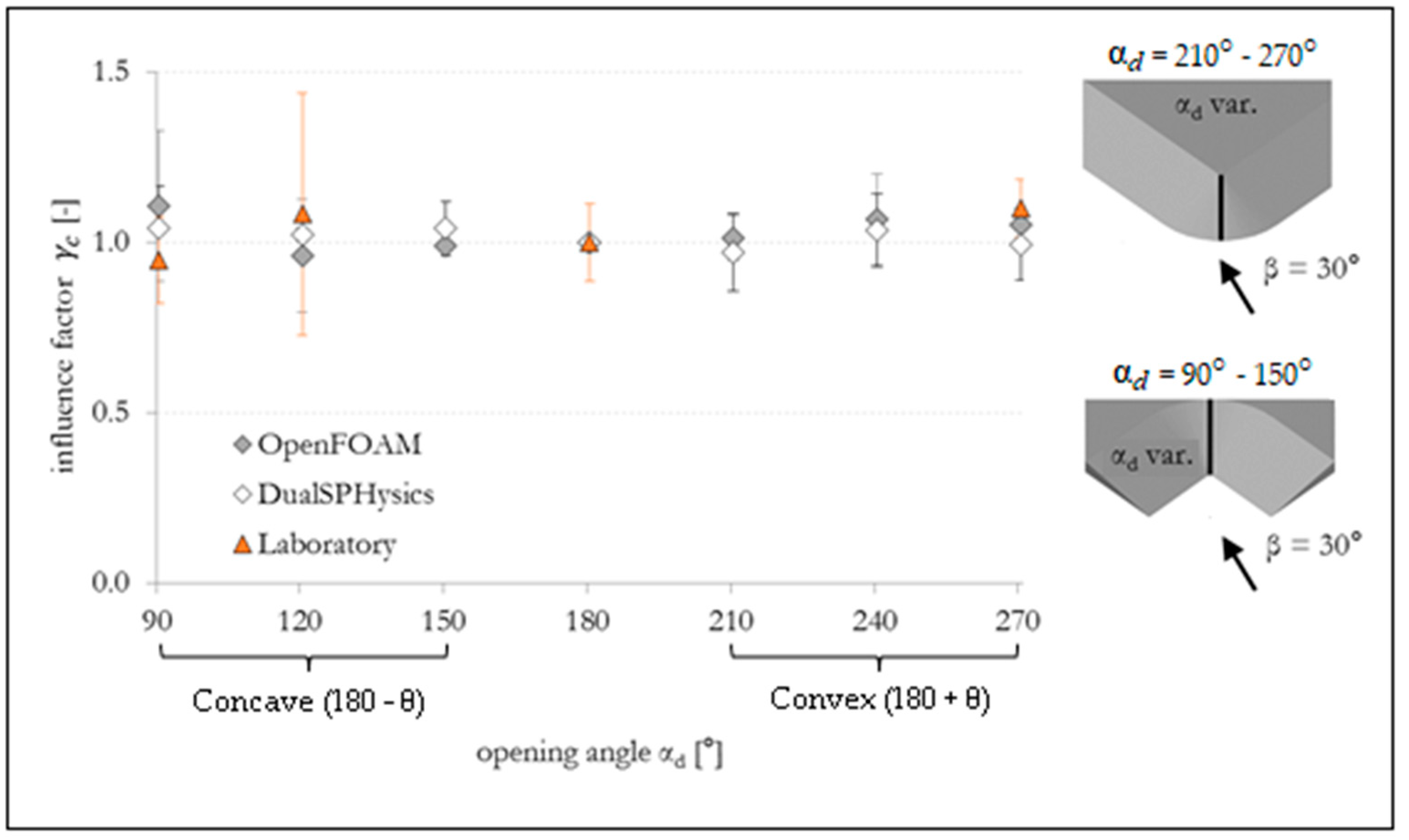
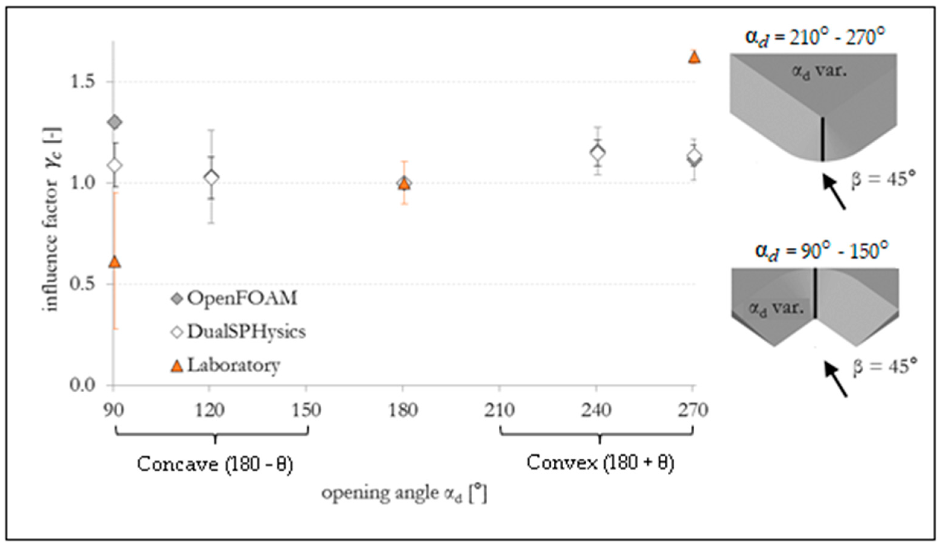
| Opening Angle αd. | Influence Factors (Position: Center of Curvature) | ||||||||
|---|---|---|---|---|---|---|---|---|---|
| β = 0° | β = 30° | β = 45° | |||||||
| Open FOAM | Dual SPH | Phys. Model | Open FOAM | Dual SPH | Phys. Model | Open FOAM | Dual SPH | Phys. Model | |
| 90° | 1.20 | 1.10 | 1.25 | 1.11 | 1.04 | 0.95 | 1.30 | 1.09 | 0.61 |
| 120° | 1.11 | 1.03 | 1.09 | 0.96 | 0.97 | 1.08 | 1.03 | 1.02 | – |
| 150° | 1.03 | 1.02 | – | 0.99 | 1.04 | – | – | – | – |
| 180° | 1.00 | 1.00 | 1.00 | 1.00 | 1.00 | 1.00 | 1.00 | 1.00 | 1.00 |
| 210° | 1.05 | 1.00 | – | 1.01 | 0.97 | – | – | – | – |
| 240° | 1.12 | 1.17 | – | 1.07 | 1.04 | – | 1.15 | 1.15 | – |
| 270° | 1.09 | 1.04 | 1.32 | 1.05 | 1.00 | 1.10 | 1.12 | 1.17 | 1.62 |
© 2019 by the authors. Licensee MDPI, Basel, Switzerland. This article is an open access article distributed under the terms and conditions of the Creative Commons Attribution (CC BY) license (http://creativecommons.org/licenses/by/4.0/).
Share and Cite
Subramaniam, S.P.; Scheres, B.; Schilling, M.; Liebisch, S.; Kerpen, N.B.; Schlurmann, T.; Altomare, C.; Schüttrumpf, H. Influence of Convex and Concave Curvatures in a Coastal Dike Line on Wave Run-up. Water 2019, 11, 1333. https://doi.org/10.3390/w11071333
Subramaniam SP, Scheres B, Schilling M, Liebisch S, Kerpen NB, Schlurmann T, Altomare C, Schüttrumpf H. Influence of Convex and Concave Curvatures in a Coastal Dike Line on Wave Run-up. Water. 2019; 11(7):1333. https://doi.org/10.3390/w11071333
Chicago/Turabian StyleSubramaniam, Suba Periyal, Babette Scheres, Malte Schilling, Sven Liebisch, Nils B. Kerpen, Torsten Schlurmann, Corrado Altomare, and Holger Schüttrumpf. 2019. "Influence of Convex and Concave Curvatures in a Coastal Dike Line on Wave Run-up" Water 11, no. 7: 1333. https://doi.org/10.3390/w11071333