Investigation of the Pressure Fluctuation Alleviation in a Hydraulic Turbine by Runner Modification

1
College of Energy and Electrical Engineering, Hohai University, Nanjing 210098, China
2
College of Water Conservancy and Hydropower Engineering, Hohai University, Nanjing 210098, China
3
Beijing Institute of Control Engineering, Beijing 100094, China
*
Author to whom correspondence should be addressed.
Water 2019, 11(7), 1332; https://doi.org/10.3390/w11071332
Submission received: 29 May 2019
/
Revised: 24 June 2019
/
Accepted: 26 June 2019
/
Published: 28 June 2019
(This article belongs to the Section Hydraulics and Hydrodynamics)
Abstract
:Cavitation and system instability are the most common problems occurring in hydraulic power systems, especially operated under part-load conditions. Previous research show that when the hydraulic turbine operates apart from designed conditions, such as part-load conditions, a helical vortex rope occurs from the runner exit, and usually generates severe pressure oscillations. Cavitation usually appears and turns the rope to become a two-phase cavitation rope. The occurrence of cavitation rope is believed to be the main reason of the severe pressure oscillations. Based on a new multiphase flow simulation method re-developed in ANSYS CFX, this paper did the runner modification by using grooves and made the investigation of pressure fluctuation alleviation in a hydraulic turbine at different cavitation numbers. The behavior of cavitation rope and the pressure fluctuations induced by cavitation under typical part load conditions with modified runner were analyzed in present research. The results show that besides the pressure fluctuation induced by the rope rotating, cavitation induced a new pressure fluctuation with a lower frequency. For the embedded analysis the results show that the modified runner can decrease the vortex rope eccentricity and increase the vortex core pressure and finally alleviate the two types of pressure fluctuations. Also, the turbine efficiency has a little rise when equipped with the modified runner.
1. Introduction
High quality and safe power is an important guarantee for industrial production and people’s daily life. In modern society, a large consumption of sources is a vital obstacle for the development of society and high technologies. The greenhouse effect and environmental pollution are prominent consequences caused by overusing fossil fuels to generate electric energy. So, developing renewable sources such as water energy, wind energy, nuclear energy are the main directions to generate electric energy. Among them, water energy converted to electric energy has advantages of low pollution and recycling. It is well known that hydro turbines can boot and shutdown rapidly. Hydraulic power has some advantages of easy storage and flexible power generation, so it therefore plays a role of power control of the grid, making it an irreplaceable power source in the electrical grid. Thus, it is a fact that operating conditions of hydro turbines is in a wide range [1]. When hydraulic turbines operated at part-load conditions, a series of negative problems such as high amplitude pressure fluctuations, dominant frequency and secondary flow occurred. Among these, cavitation and system instability are the most common problems occurring in hydraulic power systems [2].
Because of operating flexibility of hydraulic turbines, it is often operated at off-design conditions, which leads to the existence of circumferential velocity, sometimes intensively, at outlet of the runner. This phenomenon means that water will shift to draft tube wall when it flows out from the runner cone, so that in the center of draft tube there is now a dead water region [3,4] with the characteristics of low pressure and low axial velocity, which induces cavitation which we call the “vortex rope” [5] or “cavitation vortex rope” [6]. This dead water region will have a circumferential velocity because its external water has an intensive circumferential velocity, rotating at a certain speed in draft tube conical part. The rotating vortex rope, with a certain times of runner rotating frequency, induces pressure fluctuations at the draft tube wall [7], mechanical vibration [8,9] and noise for entire hydraulic turbines. Model and prototype tests, as well as CFD method, have been carried out to investigate the mechanism of vortex rope and pressure oscillations. Kirschner [1] analyzed low frequency characteristics induced by vortex rope rotation through experiments. Nicolet et al. [10] analysed pressure fluctuations through experiments and Müller A [11] investigated vortex rope features in the axial and tangential velocity perspective, respectively. Hydraulic model experiments, especially prototype tests, have high reliable results for analysis of cavitation vortex rope, but we have difficulty to catch the details of flow regimes in that way, in addition, its experimental expenses are huge, and high accurate devices cost a lot. Therefore, numerical simulations as a developing method is more convenient for capturing the flow regime details and hence used widely. However, for the numerical methods, large eddy simulations (LES) have been used and some other turbulent models such as Reynolds stress models (RSM) also have a high accuracy in vortex rope investigations, all of them are proved in [12,13,14,15]. Up to now, many researchers have proved that numerical investigations can be a very useful method in draft tube investigations [16,17].
As can be seen, a lot of work has been carried out to satisfy the demand of mitigating the damage of vortex rope and pressure fluctuations. Several researches have been conducted to mitigate these effects, for instance, by adding fins on the draft tube wall [18], hydraulic runner’s optimized design [19], water injection [20,21]and aeration [22,23]. They all play a part in suppressing pressure fluctuations at draft tube wall and optimizing velocity fields of runner discharge. Nevertheless, the method of water injection and aeration needs auxiliary equipment, which has a high cost, and also, the auxiliary equipment will produce extra hydraulic loss. Hydraulic power plants hope that the problem can be solved during the design process, and that no auxiliary equipment will be needed. Thus, runner modification has been done to alleviate the pressure fluctuations which are caused by the swirl flow.
Cavitation rope develops from runner cone, and its flow regimes play a vital role in the formation and evolution of the vortex rope [24]. Gogstad and Dahlhaug [25] used runner cone extension to reduce tangential component of the velocity in the runner exit and dampen pressure fluctuations.
In this research, the objective is to put forward a modified runner and verify its validity on alleviating the pressure fluctuations and other problems induced by cavitation rope in the draft tube. This modified runner should have a minimum cost and low hydraulic loss, and should not need auxiliary equipment. Then, this study will compare the unsteady behavior in the Francis turbine of two runners with and without modification. This paper uses a new multiphase simulation method coupled with a modified PANS (partially averaged Navier-Stokes) turbulence model to research the vortex rope features and pressure pulsations of a model turbine with and without a modified runner. First of all, this paper will verify the accuracy of numerical simulation in pressure fluctuations with comparison to experiments by using mathematical method fast fourier transform (FFT). Most importantly, this study will prove the alleviating effects on vortex rope evolution and pressure fluctuations of a modified runner.
2. Mathematical Model
Different turbulent models are suitable to be applied in numerical conditions and their accuracy is different. A suitable mathematical model used for the simulation can ahcieve accurate results corresponding to the experiments. Recently, Huang [26] introduced the level set method into cavitating flow and proved its advantages in capturing the interface between vapor and water. Then, Yu et al. [27] developed a new multiphase flow simulation method, which consisted of the level set model and modified k-ε turbulence model, and proved its effectiveness and advancement for reflecting the characteristics of the multiphase flow in the investigation of cavitating flow around a cylinder body.
In multiphase flow simulation, such as cavitating flow of vapor and liquid, a homogeneous hypothesis was a comprehensive method where vapor and liquid are treated as a mixed substance. Governing equations for mixture are shown as follows:
where ρ is density, u is time averaged velocity and p is relative pressure. The subscript of m represent the mixture. μm is the mixture molecular viscosity and μt is turbulent viscosity is based on the Boussinesq hypothesis.
Since surface tension is the main force acting at the interface of the water and vapor, Equation (2) kept the surface tension term, with κand σsrepresenting the surface curvature and surface tension coefficient, and n representing a direction vector point to the second fluid from the primary fluid, respectively.
Accurate interface between water and vapor is vital for multiphase fluid simulation, so one interface tracking method must be used in the present study. Level-set method can capture clear vapor-liquid interface and it is reflected by function δ, becoming adopted into the simulation. Therefore, in governing equations, besides modifying the density and viscosity of the mixture flow, the level-set function δ is used to turn the surface tension force to be a calculable source term.
LES (large eddy simulation) has been proven to have a high accuracy in predicting cavitating flows [28,29]. It simulates the large-scale turbulences directly, while modelling the small-scale turbulences in SGS (sub grid-scale stress) under an isotropy assumption. Although LES has a high accuracy, it requests large computing resource. Thus, LES has not been widely used in the investigations in hydraulic turbines. In this research, a modified partially averaged Navier-Stokes (PANS) model was used in simulation for its high accuracy, and it is an improvement of original PANS model. The original PANS method is a mixed model induced from k-ε model, which can bridge RANS and DNS (direct numerical simulation) models by using kinetic energy (fk = ku/k) and dissipation (fε = εu/ε). The equations of original PANS model is as follows:
where Cε1 = 1.44, σk = 1.0 and σε = 1.3. The subscript u is the PANS unresolved quantities. The challenge for original PANS model is to determine the lowest fk distribution, where a given grid can support the specific flow.
In the original PANS model, the lowest fk is a constant value and is determined by the users. Instead of a constant value, the modified PANS model used a self-adapting fk and has been proven for its feasibility and reliability in cavitating flow simulation [30]. The fk is defined as:
where Δ = (Δx × Δy × Δz)1/3 is the local grid size.
Yang [31] compared FBDCM (filter based density correction model) and modified PANS model in ventilation cavitation, and proved that modified PANS model is more preferable than FBDCM model in engineering applications. For hydraulic turbines, Yang [32] used modified PANS model in pump-turbine predicting the slope characteristics at pump mode and got more accurate results compared to RANS model. The application shows that the modified PANS can be used for cavitating turbulent flow [33]. A modified PANS model, owing to its more accurate results [30], has been proposed in this research.
The modified PANS model was adopted coupled with Zwart cavitation model to simulate the cavitating vortex flow in the hydro turbine. The mass transport equation for vapor can be written as follows:
where the subscript of v represents the vapor and α is the volume fraction. The source terms due to vaporization and condensation in the cavitation model are presented as Equations (10) and (11):
where Ce, Cc are the evaporation and generally condensation empirical parameters. The subscript v and nuc represents vapor and undissolved gas nucleation respectively. Rb = 5 × 10⁻⁵ m is bubble radius.
In this article, the two-phase flow was simulated using the new multiphase flow simulation method, which is proposed in the previous works [26]. Also, the modified PANS model, which is used in capturing the unsteady flow around hydrofoils, was also introduced into the hydro turbine simulation.
3. Grids and CFD Set Up
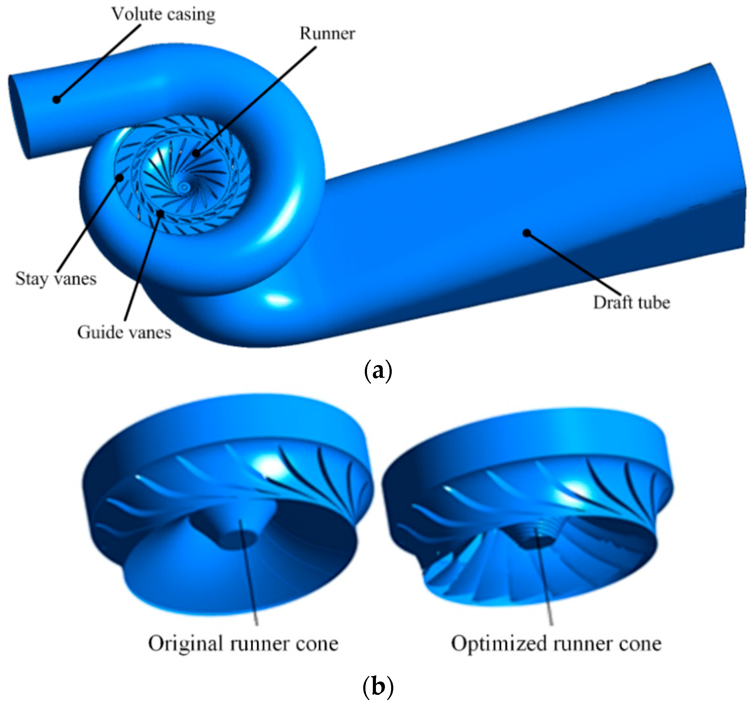
This present study aims to compare the performance of original and modified runner by their suppressible effects on amplitude of pressure fluctuations and frequency induced by cavitation vortex rope forming from runner cone. The structure of the whole passage of the model turbine was used as the computational domain and the modified runner is shown in Figure 1. Table 1 shows the fundamental structure parameters of model turbine and guide vane opening conditions. Six vortex-control grooves were set on the modified runner cone, which have an opposite direction with the runner rotating direction. A typical part-load operating conditions with two cavitation numbers (σ = 0.12, σ = 0.03) were investigated. Note that at σ = 0.12, no cavitation occurred, and the flow was a single-phase flow. While at σ = 0.03, cavitation occurred in the draft tube and it turned the rope into a two-phase rope.
Hexa-structural mesh was adopted in this simulation for whole computational domain, because it can better adapt to the complicated shape of domain and can get accurate results. Mesh independence was done before investigations and the results are shown in Table 2. The computational domain with different runners have the same mesh numbers. After mesh independence validation, the case of about 3,200,000 nodes and 2,130,000 elements was used in the investigations with a consideration of balancing the accuracy and computational capability. The y+ is 29 with this mesh.
The research was conducted by using the commercial software ANSYS CFX 16 with secondary development. The equations of modified PANS were written in the expression of CFX and simulated under CFX environment. The time-dependent governing equations were discretized both in space and time. In this simulation, we set 0.001102 s (6 degree per time step) as the initial calculation time step, and after several runner revolutions, we set it to 0.0001837 s (1 degree per time step) as a numerical time step. For the interface between stationary and rotating parts, a slipping mesh was applied on this unsteady hydraulic turbine simulation. Total pressure was assigned at the domain inlet, and the static pressure was assigned at the draft tube outlet. All solid walls had nonslip boundary conditions. The detailed value of the boundary conditions are shown in Table 3.
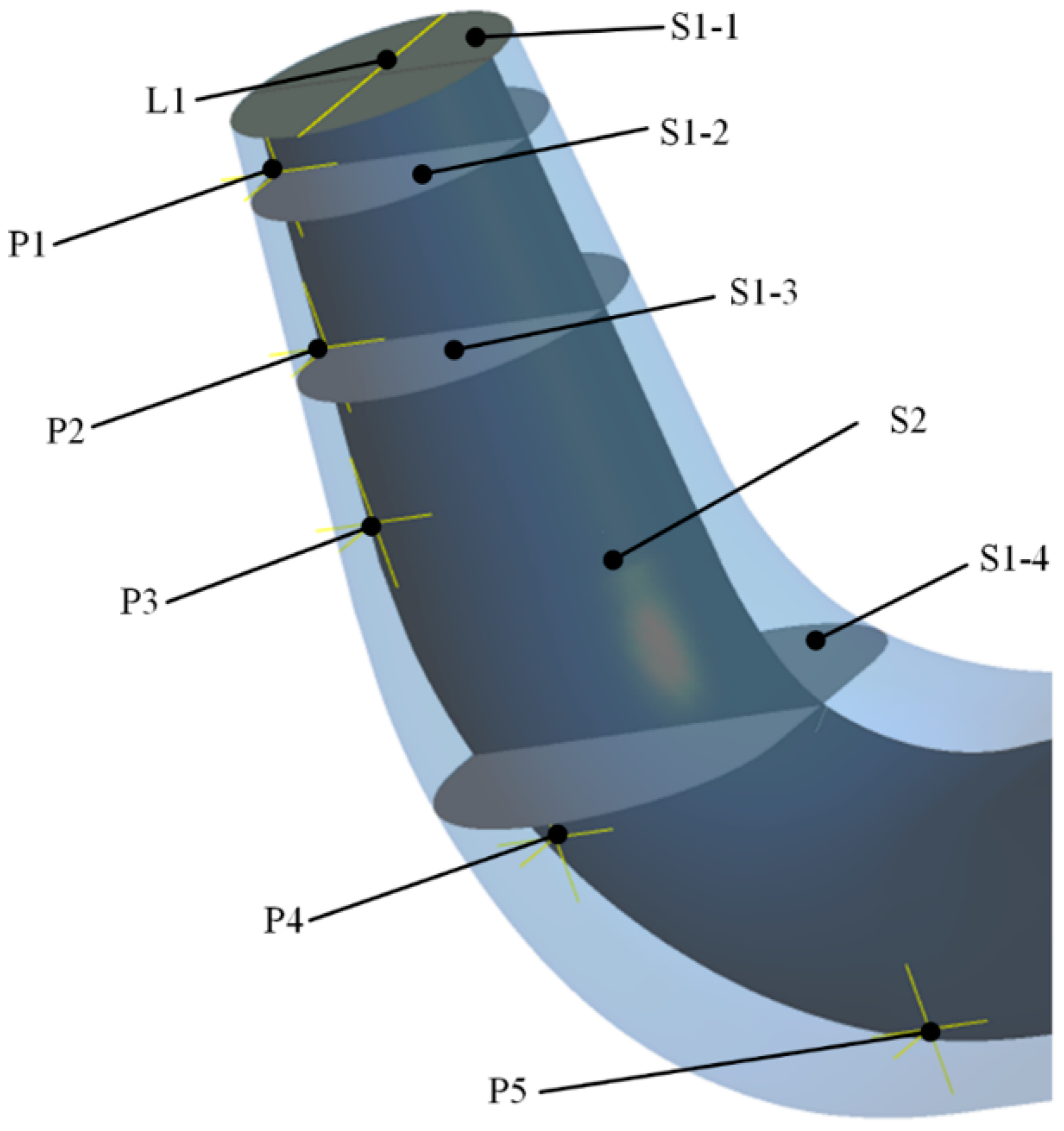
For the purpose of obtaining the detailed flow characteristics and compare with experimental data, five reference sections were set, as shown in Figure 2, which is at the same position with the experiment. The section S1-1 is the draft tube inlet. The distance from other sections S1-2, S1-3, S1-4 to draft tube inlet is 0.5D1, 1.5D1, and 3.5D1, respectively. Section S2 is a plane along the center line and the monitoring points P1 to P5 are on the intersecting line of the monitoring section 1-1 and the monitoring section 2. The monitoring line L1 was a diameter of section S1-1. Also, several monitoring points were set on the draft tube wall.
4. Results and Discussion
The internal flow characteristics were investigated with the original and modified runner. The main emphasis was on the vortex rope behavior and pressure fluctuation alleviation. The pressure fluctuations with the original runner were first discussed, while alleviation of the pressure fluctuations was discussed in the second subsection. At last, the vortex rope behavior and the inner flow characteristics was discussed in subsection 3.
4.1. Pressure Fluctuations under Part Load Condition with Original Runner
As mentioned before, this paper aims to compare pressure fluctuations performance of the Francis turbines with original and modified runner when turbines operated at two typical part-load conditions, i.e., two cavitation numbers σ = 0.12, σ = 0.03. At cavitation number σ = 0.12, no cavitation occurred and the vortex rope is a single-phase rope. While at σ = 0.03, cavitation occurred and turned the vortex rope to be a two-phase cavitation rope.
The computed results with the original runner are verified by comparison with experiment data (measured at Harbin Electric Company Ltd, Haerbin, China) [34], and the flow characteristics are shown at Table 4. The results used a conventional simulation method for comparison, which contained a mixture multiphase model and SAS-SST turbulence model [34]. The simulation results with the present simulation method and experimental data agreed very well in dominant-frequency (which has the biggest amplitude) component both at σ = 0.12 and σ = 0.03. The reason of formation of the low-frequency is the rotation of cavitation vortex rope, which has been proved by many other studies. Also, results show that the present simulation method can obtain a more accurate flow rate and efficiency compared with conventional simulation method.
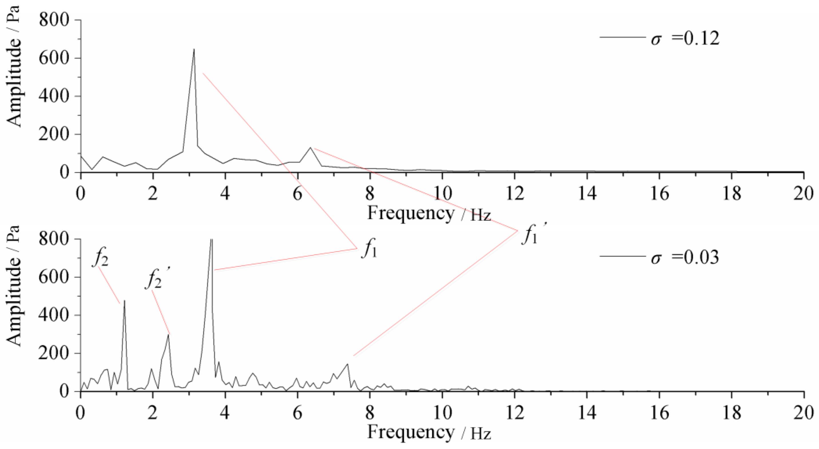
As shown in Figure 3, there are pressure pulsation observed at draft tube wall (monitor point P1) without runner modification at different cavitation numbers (σ = 0.12, σ = 0.03). After numerical simulation, fast fourier transform (FFT) was adopted to get frequency and amplitude. As we can see, only one dominant frequency (f1) and its harmonic (f1’) were induced by vortex rope at non-cavitation condition (σ = 0.12). With the decreasing of cavitation number, other types of pressure fluctuation frequency occur and dominant frequency (f1) changed. At cavitation number 0.03 (σ = 0.03) conditions, two-phase cavitation vortex rope occurred and it induced another lower frequency f2 (where f2’ is the harmonic wave of f2). Other than that, the dominant frequency f1 increased a little at σ = 0.03 than σ = 0.12.
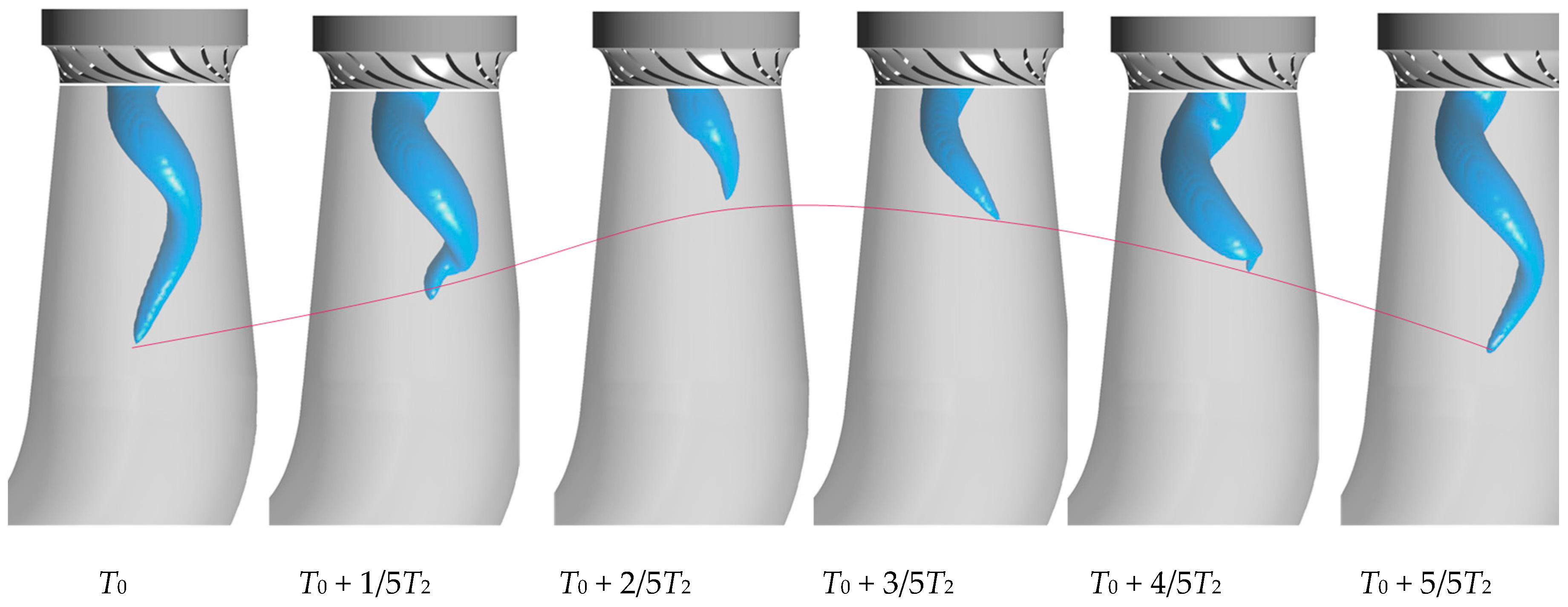
Combined with other researchers’ previous studies, it can be indicated that the pressure pulsation of f1 is induced by the vortex rope rotating. In order to make a clear understanding of the causing reason of the pressure fluctuation f2, the cavitation rope behavior in typical periods was structured with iso-surface vapor volume fraction of 0.1. Figure 4 shows the cavitation rope behavior with a typical period (the period is T2, which is corresponding to pressure fluctuation f2). It is indicated that besides rotating with the frequency of f1, the length of the cavitation rope changes a lot, while the diameter of the cavitation rope changes a little (the red line is the tailing part of the vortex rope, which can reflect cavitation rope length). Thus, the volume of the cavitation rope changes periodically and the frequency of the cavitation volume change is the same with pressure fluctuation f2. Thus, the pressure fluctuation f2 is induced by cavitation volume change.
4.2. Pressure Fluctuation Alleviation with Modified Runner
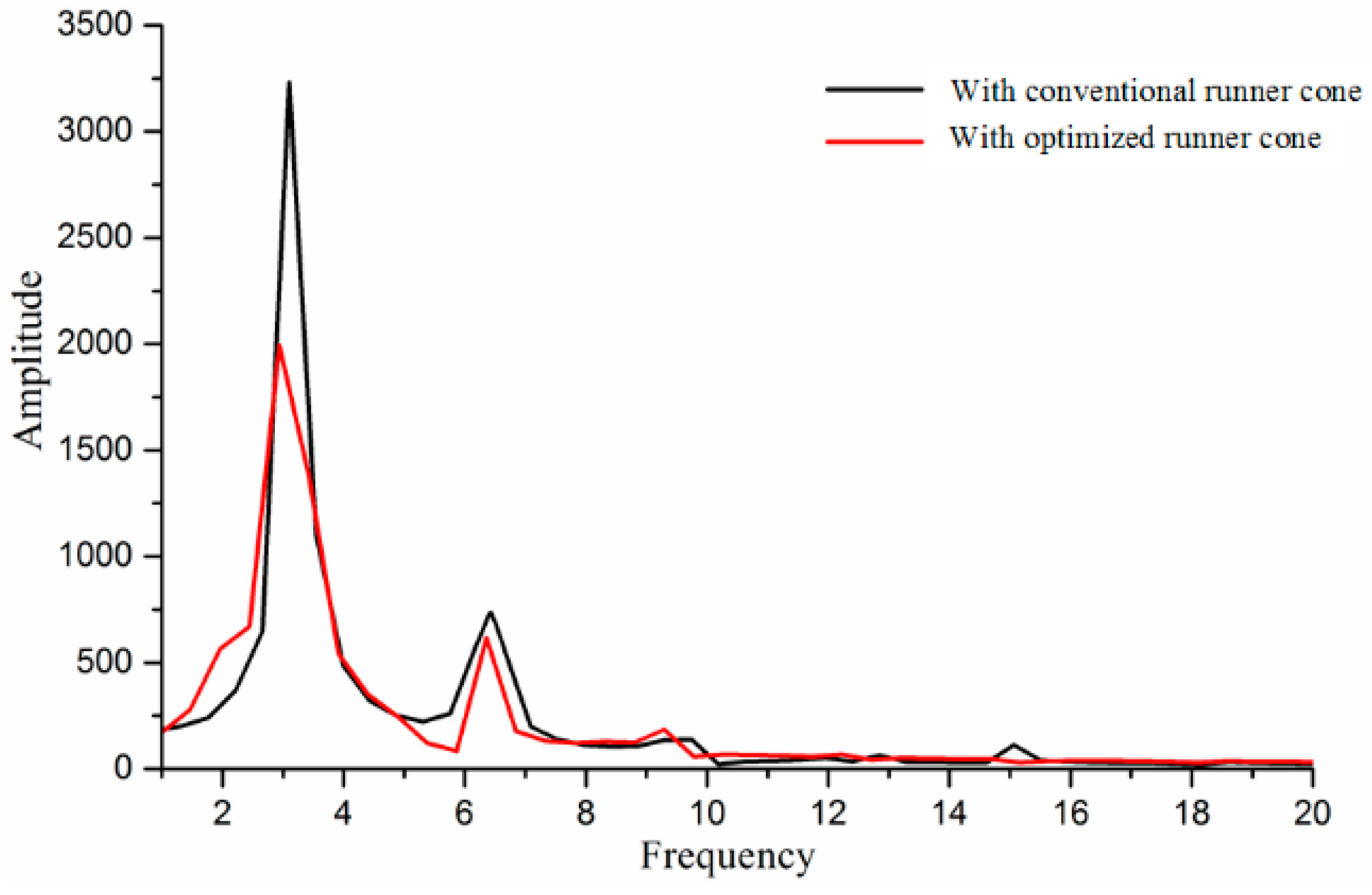
When hydraulic turbines operated under part-load conditions, circumferential component of the flow velocity appeared in the runner exit, and has the same direction with the runner rotating. Since the formation of vortex rope has a great correlation with the swirling flow near the runner exit, depressing the swirl flow can be an effective way to alleviate the pressure fluctuations. Thus, six vortex-control grooves were set on the optimized runner cone and were supposed to optimize the velocity field, especially circumferential velocity, at the outlet runner and runner cone to alleviate swirling flow. In order to compare the performance of original and grooved runner cone, pressure fluctuations of point P1 was shown in Figure 5 (σ = 0.12) and Figure 6 (σ = 0.03). It is noted that the modified runner can obviously mitigate the amplitude of pressure fluctuation f1, and the pressure amplitude decreased more than 35%, while the frequency has also decreased a little.
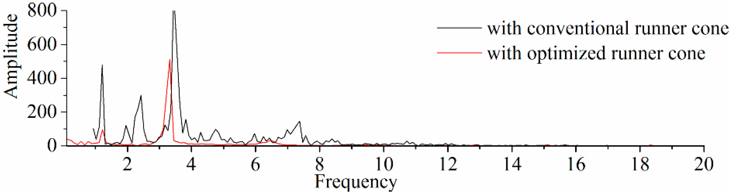
Figure 6 shows the pressure fluctuations at cavitation number σ = 0.03, both of the amplitudes of the two types pressure fluctuations decreased. The amplitude of pressure fluctuation f1 decreased more than 37%, while amplitude of pressure fluctuation f2 decreased more than 80%. It indicates that not only can the new runner cone mitigate the amplitude of frequency f1 induced by vortex rope rotating and frequency f2 caused by cavitation volume change, but can also decrease dominant frequency f1 a little, as shown in Figure 5 and Figure 6.
4.3. Vortex Rope Behavior and the Inner Flow Characteristics
Previous investigations indicated that the pressure fluctuations at part-load conditions are closely connected with the vortex rope behavior. As mentioned before, the modified runner can decrease the amplitude of pressure fluctuations and cavitating effects apparently. Therefore, the new runner may have a positive effect on the behavior of cavitation rope to optimize the velocity field for outlet of runner and inner draft tube.
Table 5 shows the average efficiency at different cavitation numbers with the original runner cones and grooved runner cone. It is indicated that the optimized runner cone can also increase the turbine efficiency besides alleviating the pressure fluctuations.
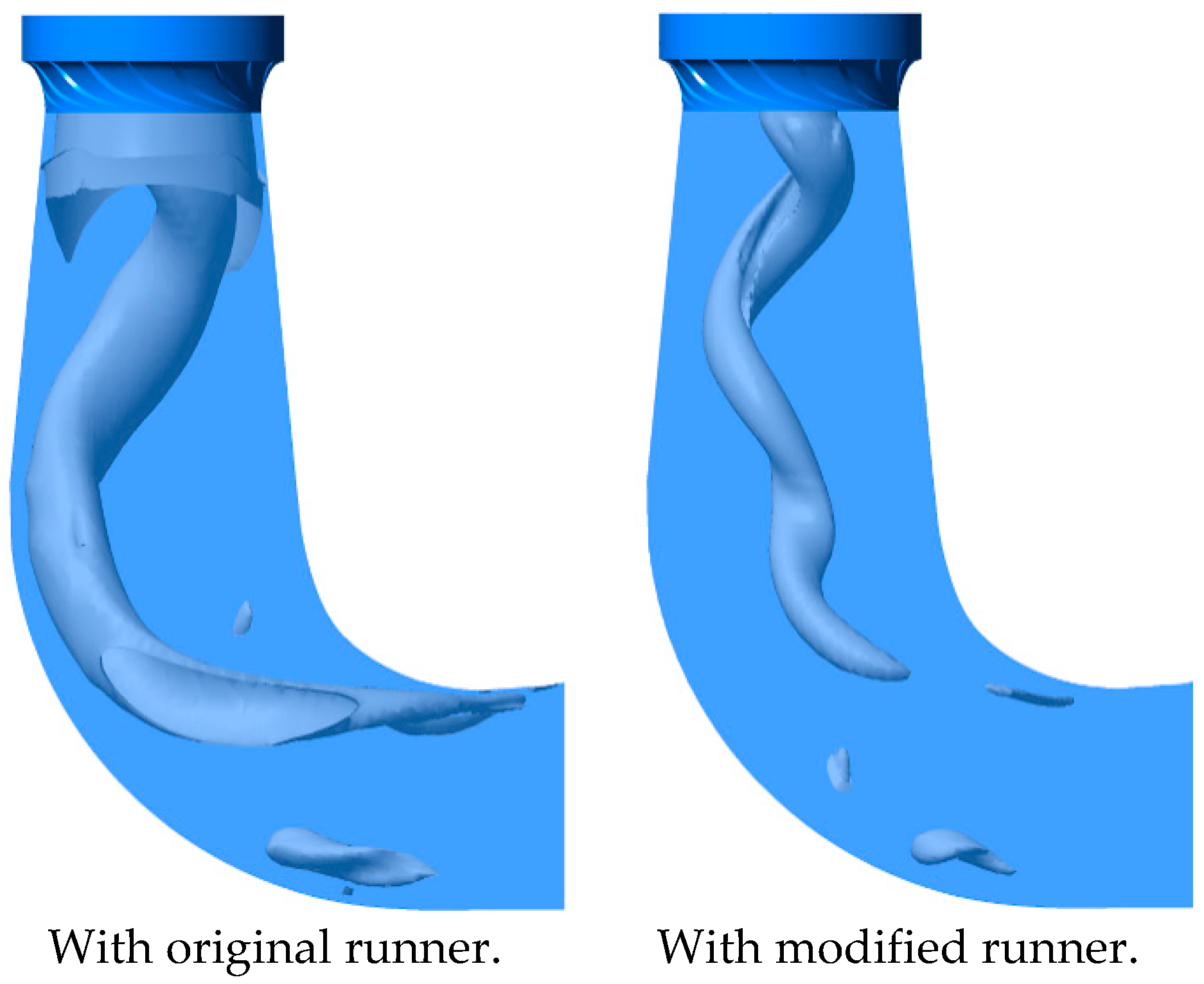
Swirling fluid regimes induces a series of damage problems, and intensive velocity swirl is the dominant reason for forming the swirling flow, i.e., the vortex. Q-criterion [32] is a comprehensive method used to identify the structure of vortex, which assists us to realize the shape and dynamic features of vortex rope. In this research, as shown in Figure 7, we used Q-criterion to identify the three-dimensional structure of vortex rope with original and grooved runner cone. From the perspective of vortex rope shape, the rope with the grooved runner cone has a smaller size compared to the original runner cone. It also indicates that with an original runner the swirling flow is very strong, and the vortex rope extends to the elbow part of draft tube. It also has a thinner and shorter rope when the runner modification was equipped. So, we conclude that the runner modification can mitigate the swirling flow and then short the vortex rope.
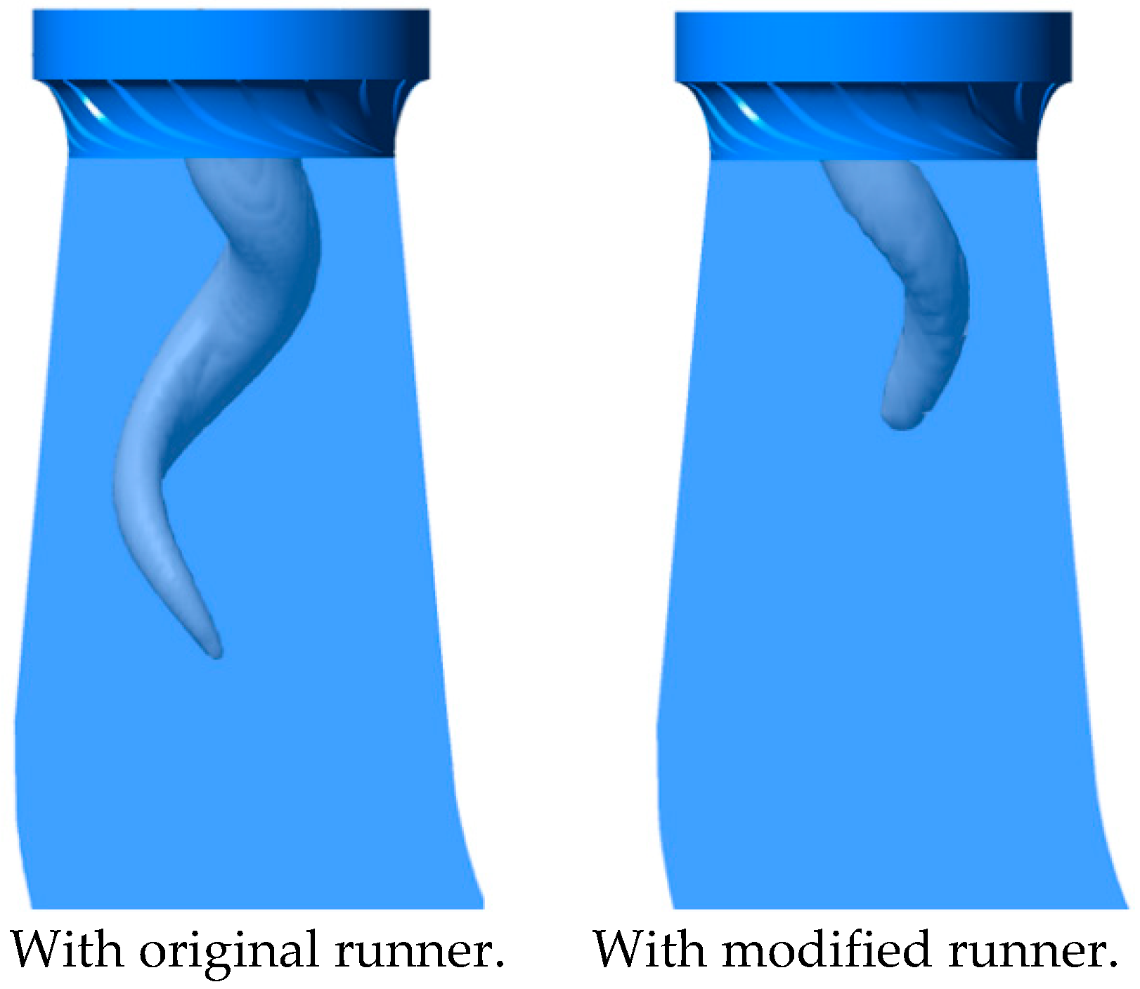
Pressure fluctuation of f2 appears together with the cavitation phenomenon and is caused by the cavitation volume change. Thus, cavitation vortex rope structure is obtained by using the iso-surface of vapor volume fraction of 0.1, as shown in Figure 8. Note that both of the ropes with two runners showing in the figure is at the same position of a cycle and both at the maximum length. Based on analysis of Figure 8 it can be indicated that the modified runner can reduce the formation of cavitation and mitigated the amplitude of frequency f2, apparently.
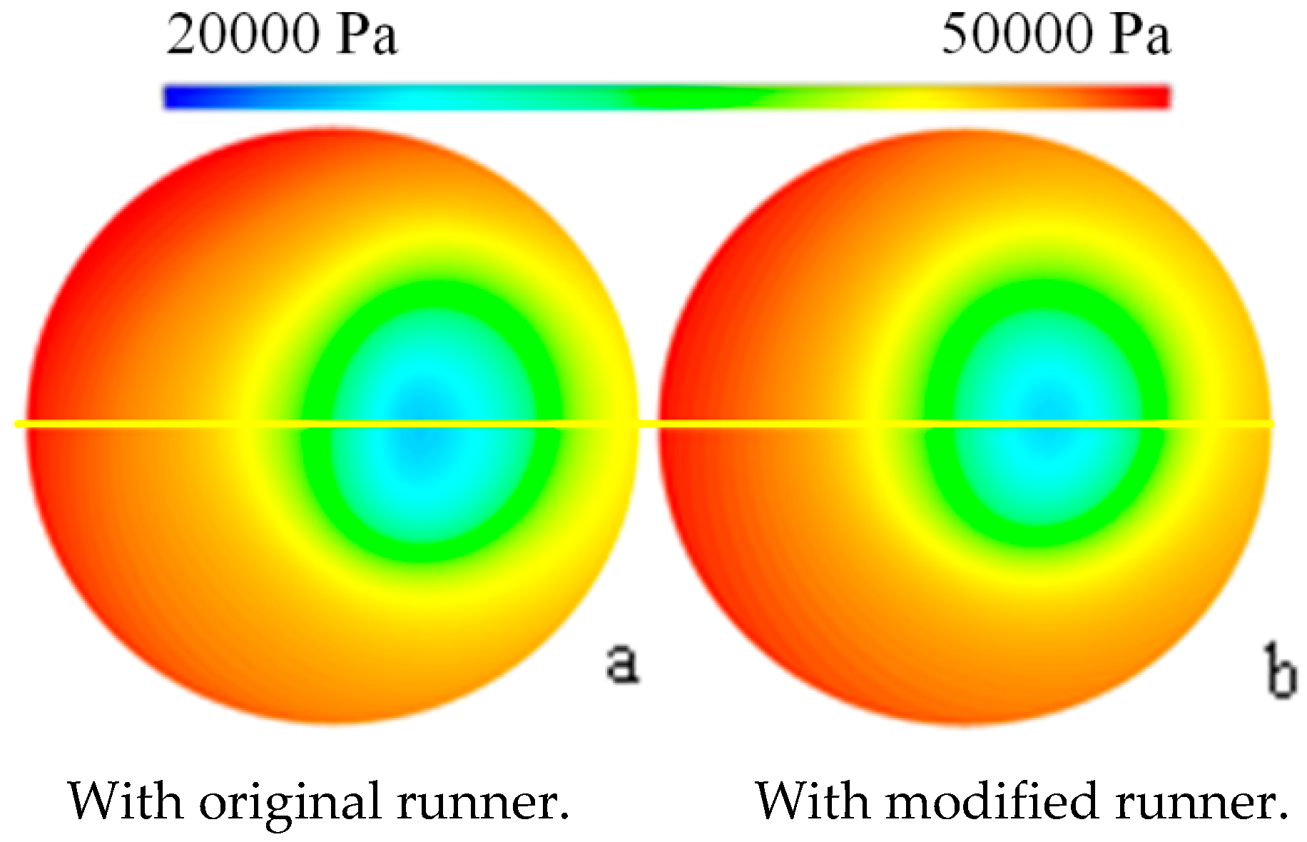
Figure 9 shows the pressure distribution in monitor section S1-1. In the instantaneous of Figure 9, the vortex rope center rotates to the right side of the section. Figure 9 also shows that with the modified runner, the center of the vortex rope moves to the section center. This means the eccentricity of the vortex rope decreased, which is a positive impact on pressure fluctuation alleviation. Also, Figure 9 shows that the pressure of the vortex core is a little higher than the case with the modified runner. In summary, the modified runner can mitigate the pressure fluctuations by decreasing the vortex rope eccentricity and increasing the pressure of the vortex core.
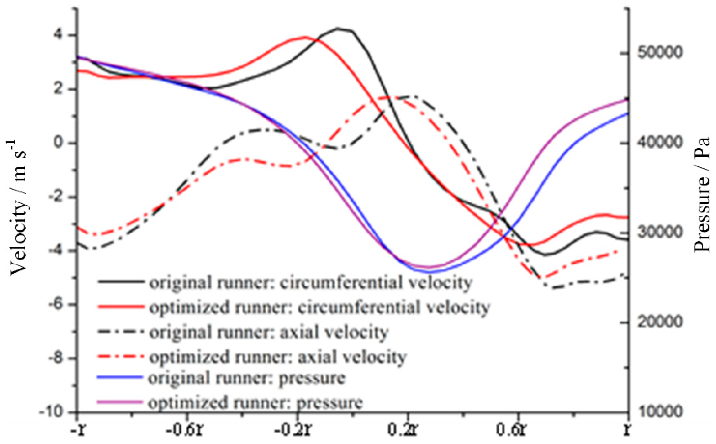
In order to make a clear understanding of the internal flow characteristics, pressure distribution and velocity distribution along a diameter are shown in Figure 10. The diameter is shown in Figure 9 (the yellow line), which passes through the vortex rope core. In Figure 10, all peaks and valleys of curves for the optimized runner cone move a little left compared to conventional one. This means its eccentricity ratio becomes smaller and this can be beneficial to the alleviation. For the circumferential component of optimized runner cone, it is much smaller than that of the original one in the regions of vortex edge. This indicates that in the near region of the grooved runner cone a reverse swirl flow forms, which then neutralizes the positive swirling flow, and finally alleviates the pressure fluctuations and cavitation evolution.
5. Conclusions
The internal flow in a model turbine operated under classical part load conditions was simulated using a new cavitating flow simulation method. During the investigation, particular emphasis was set on cavitation rope behaviour and the alleviation of the pressure fluctuation. Based on the present investigation, it can be concluded that:
1. The present simulation method has a better accuracy for predicting hydraulic performance and pressure fluctuations in a Francis turbine. From the results, it can be obtained that only one low pressure pulsation frequency without cavitation occurred, which is induced by the vortex rope rotating. Whereas, when the cavitation number is 0.03, a new pressure fluctuation induced by cavitation volume change with a lower frequency occurs.
2. With the modified runner, the pressure fluctuations caused by vortex rotating decreased more than 35%, while the pressure fluctuation caused by cavitation volume change decreased about 80%. Also, the frequency of pressure fluctuations caused by the vortex rotating changed a little.
3. In the near region of runner cone, a reverse swirl flow was generated to slow down the main vortex flow and increase the turbine efficiency. Also, the vortex rope eccentricity decreased and the pressure of the vortex core increased by using the modified runner. Thus, the runner modification can alleviate the pressure fluctuations by reducing swirling flow intensity and suppressing the cavitation phenomenon.
Author Contributions
Conceptualization, A.Y. and D.Z.; methodology, A.Y.; software, Q.T. and J.L.; validation, A.Y., and D.Z.; formal analysis, A.Y.; investigation, A.Y.; data curation, A.Y.; writing—original draft preparation, X.W.; writing—review and editing, A.Y.; visualization, A.Y.; supervision, A.Y.; project administration, A.Y.; funding acquisition, A.Y.
Funding
This research was funded by the National Natural Science Foundation of China (Project No. 51806058) and the Fundamental Research Funds for the Central Universities (Project No. 2019B15014).
Conflicts of Interest
The authors declare no conflict of interest.
References
- Kirschner, O.; Ruprecht, A.; Göde, E.; Riedelbauch, S. Experimental investigation of pressure fluctuations caused by a vortex rope in a draft tube. In Proceedings of the 26th IAHR Symposium on Hydraulic Machinery and Systems, Beijing, China, 19–23 August 2012. [Google Scholar]
- Celebioglu, K.; Altintas, B.; Aradag, S.; Tascioglu, Y. Numerical research of cavitation on Francis turbine runners. Int. J. Hydrog. Energy 2017, 42, 17771–17781. [Google Scholar] [CrossRef]
- Sano, T.; Ookawa, M.; Watanabe, H.; Okamoto, N.; Yano, H.; Fukuda, N.; Maekawa, M.; Miyagawa, K. A New Methodology for Suppressing Pressure Pulsation in a Draft Tube by Grooved Runner Cone. In Proceedings of the Asme-jsme-ksme Joint Fluids Engineering Conference, Hamamatsu, Japan, 24–29 July 2011. [Google Scholar]
- Sano, T.; Maekawa, M.; Okamoto, N.; Yano, H.; Miyagawa, K. Investigation of flow pattern downstream of spiral grooved runner cone in pump-turbine. Earth Environ. Sci. 2012, 15, 022019. [Google Scholar] [CrossRef]
- Skripkin, S.; Tsoy, M.; Kuibin, P.; Shtork, S.; Markovich, D.; Zaitsev, D.; Semenov, A. Vortex rope instabilities in a model of conical draft tube. EPJ Web Conf. 2017, 159, 48. [Google Scholar] [CrossRef] [Green Version]
- Wack, J.; Riedelbauch, S. Numerical simulation of a cavitating draft tube vortex rope in a Francis turbine at part load conditions for different σ-levels. J. Phys. Conf. Ser. 2017, 813, 012109. [Google Scholar] [CrossRef]
- Matsuzaka, R.; Nakashima, T.; Miyagawa, K. Study on flow instability in a diffuser with swirling flow under several conditions of pipe length and swirl intensity. In Proceedings of the 28th IAHR Symposium on Hydraulic Machinery and Systems, Grenoble, France, 4–8 July 2016; p. 082015. [Google Scholar]
- Wu, Y.; Li, S.C.; Liu, S.H. Vibration Induced by Hydraulic Excitation. In Vibration of Hydraulic Machinery; Springer: Dordrecht, The Netherlands, 2013; pp. 147–233. [Google Scholar]
- Grein, H. Vibration Phenomena in Francis Turbines: Their Causes and Prevention. In Proceedings of the 10th IAHR Symp, Tokyo, Japan, 28 September–2 October 1980. [Google Scholar]
- Nicloet, C.; Zobeiri, A.; Maruzewski, P. On the upper part load vortex rope in Francis turbine: Experimental investigation. Earth Environ. Sci. 2010, 12, 12053. [Google Scholar] [CrossRef]
- Zhang, Y.N.; Chen, T.; Li, J.; Yu, J.X. Experimental study of load variations on pressure fluctuations in a prototype reversible pump turbine in generating mode. J. Fluids Eng.-ASME 2017, 139, 074501. [Google Scholar] [CrossRef]
- Skotak, A.; Mikulašek, J.; Lhotakova, L. Effect of the inflow conditions on the unsteady draft tube flow. In Proceedings of the 21st IAHR Symposium on Hydraulic Machinery and Systems, EPFL/STI/LMH, Lausanne, Switzerland, 9–12 September 2002; pp. 284–291. [Google Scholar]
- Sick, M.; Doerfler, P.; Sallaberger, M. CFD simulation of the draft tube vortex. In Proceedings of the 21st IAHR Symp on Hydraulic Machinery & Systems, EPFL/STI/LMH, Lausanne, Switzerland, 9–12 September 2002; pp. 1–9. [Google Scholar]
- Guo, Y.; Kato, C.; Miyagawa, K. Large-eddy simulation of non-cavitating and cavitating flows in an elbow draft tube. In Proceedings of the 23rd IAHR Symposium on Hydraulic Machinery and Systems, Yokohama, Japan, 17–21 October 2006; pp. 17–21. [Google Scholar]
- Kurosawa, S.; Satou, S. Turbulent flow simulation for the draft tube of a Kaplan turbine. In Proceedings of the 23rd IAHR Symposium on Hydraulic Machinery and Systems, Yokohama, Japan, 17–21 October 2006. [Google Scholar]
- Liu, S.H.; Zhang, L.; Nishi, M. Cavitating Turbulent Flow Simulation in a Francis Turbine Based on Mixture Model. J. Fluids Eng.-T ASME 2009, 131, 051302. [Google Scholar] [CrossRef]
- Tridon, S.; Barre, S.; Ciocan, G.D.; Tomas, L. Experimental Analysis of the Swirling Flow in a Francis Turbine Draft Tube: Focus on Radial Velocity Component Determination. Eur. J. Mech. B-Fluids 2010, 29, 321–335. [Google Scholar] [CrossRef]
- Nishi, M.; Kawai, K.; Yoshida, K.; Ma, Z.; Qian, H. Installation of a fin as a means to alleviate the draft tube surging. In Proceedings of the 20th IAHR Symposium, Graz, Austria, 19 January 1999. [Google Scholar]
- Pochylý, F.; Haluza, M.; Veselý, J. The Francis Pump Turbine with Stochastic Blades. Procedia Eng. 2012, 39, 68–75. [Google Scholar] [CrossRef]
- Miyagawa, K.; Tsuji, K.; Yahara, J.; Nomura, Y. Flow instability in an elbow draft tube for a Francis pump-turbine. In Proceedings of the 21st IAHR Symposium on Hydraulic Machinery and Systems, EPFL/STI/LMH, Lausanne, Switzerland, 9–12 September 2002. [Google Scholar]
- Qian, Z.D.; Li, W.; Huai, W.X.; Wu, Y.L. The Effect of Runner Cone Design on Pressure Oscillation Characteristics in a Francis Hydraulic Turbine. J. Power Energy 2012, 226, 137–150. [Google Scholar] [CrossRef]
- Bosioc, A.I.; Susan-Resiga, R.; Muntean, S.; Tanasa, C. Unsteady Pressure Analysis of a Swirling Flow with Vortex Rope and Axial Water Injection in a Discharge Cone. J. Fluids Eng.-T ASME 2012, 134, 081104. [Google Scholar] [CrossRef]
- Susan-Resiga, R.; Vu, T.C.; Muntean, S. Jet control of the draft tube vortex rope in Francis turbines at partial discharge. In Proceedings of the 23rd IAHR Symposium on Hydraulic Machinery and Systems, Yokohama, Japan, 17–21 October 2006. [Google Scholar]
- Baya, A.; Muntean, S.; Câmpian, V.C.; Cuzmoş, A.; Diaconescu, M.; Bǎlan, G. Experimental investigations of the unsteady flow in a Francis turbine draft tube cone. Earth Environ. Sci. 2010, 12, 0120007. [Google Scholar]
- Gogstad, P.J.; Dahlhaug, O.G. Evaluation of runner cone extension to dampen pressure pulsations in a Francis model turbine. Earth Environ. Sci. 2016, 49, 082019. [Google Scholar] [CrossRef]
- Huang, B.; Wang, G.Y.; Zhang, M.D. Level Set Method for Simulation of Cavitating Flows. J. Ship Mech. 2011, 15, 207–216. [Google Scholar]
- Yu, A.; Luo, X.W.; Ji, B. Analysis of ventilated cavitation around a cylinder vehicle with nature cavitation using a new simulation method. Sci. Bull. 2015, 60, 1833–1839. [Google Scholar] [CrossRef] [Green Version]
- Long, Y.; Long, X.P.; Ji, B.; Xing, T. Verification and validation of Large Eddy Simulation of attached cavitating flow around a Clark-Y hydrofoil. Int. J. Multiph. Flow 2019, 115, 93–107. [Google Scholar] [CrossRef]
- Long, X.P.; Cheng, H.Y.; Ji, B.; Arndt, R.E.A.; Peng, X.X. Large Eddy Simulation and Euler-Lagrangian coupling investigation of the transient cavitating turbulent flow around a twisted hydrofoil. Int. J. Multiph. Flow 2018, 100, 41–56. [Google Scholar] [CrossRef]
- Huang, R.F.; Luo, X.W.; Ji, B.; Ji, Q. Turbulent flows over a backward facing step simulated using a modified Partially-Averaged Navier-Stokes model. J. Fluids Eng.-T ASME 2017, 139, 044501. [Google Scholar] [CrossRef]
- Yang, D.D.; Yu, A.; Ji, B.; Zhou, J.J.; Luo, X.W. Numerical analyses of ventilated cavitation over a 2-D NACA0015 hydrofoil using two turbulence modeling methods. J. Hydrodyn. 2018, 30, 345–356. [Google Scholar] [CrossRef]
- Yang, D.D.; Luo, X.W.; Liu, D.M. Unstable flow characteristics in a pump-turbine simulated by a modified Partially-Averaged Navier-Stokes method. Sci. China Technol. Sci. 2019, 62, 406–416. [Google Scholar] [CrossRef]
- Huang, R.F.; Luo, X.W.; Ji, B. Numerical simulation of the transient cavitating turbulent flows around the Clark-Y hydrofoil using modified partially averaged Navier-Stokes method. J. Mech. Sci. Technol. 2017, 31, 2849–2859. [Google Scholar] [CrossRef]
- Luo, X.W.; Yu, A.; Ji, B.; Wu, Y.L.; Tsujimoto, Y. Unsteady vertical flow simulation in a Francis turbine with special emphasis on vortex rope behavior and pressure fluctuation alleviation. J. Power Energy 2017, 231, 215–226. [Google Scholar] [CrossRef]
Figure 1.
Computational domain: (a) whole passage; (b) original and modified runner.

Figure 2.
Location of monitoring sections and points.

Figure 3.
Pressure fluctuations of monitor point P1.

Figure 4.
Vortex rope behaviour in typical period structured with iso-surface of vapour volume fraction.
Figure 4.
Vortex rope behaviour in typical period structured with iso-surface of vapour volume fraction.

Figure 5.
Pressure fluctuation at σ = 0.12.

Figure 6.
Pressure fluctuations at σ = 0.03.

Figure 7.
Vortex rope structured by Q-criterion.

Figure 8.
Cavitation rope structured by iso-surface of vapour volume fraction.

Figure 9.
Pressure distribution in monitor section S1-1 at σ = 0.12.

Figure 10.
Velocity and pressure distributions along a diameter L1.


Table 1.
Model turbine structure.
| Name | Value |
|---|---|
| Runner diameter D1 | 420 mm |
| Runner blade number Zb | 17 |
| Stay vane number | 23 |
| Guide vane number | 24 |
| Height of the guide vane b0 | 18.257 mm |
| Guide vane opening α0 | 11.5 mm |
| Length of the draft tube | 3713.5 mm |
| Inlet diameter | 410 mm |
Table 2.
Mesh independence at σ = 0.12 with the present simulation method.
| Mesh Nodes Number | Outlet Discharge | Efficiency |
|---|---|---|
| 1,470,000 | 227.61 | 90.32 |
| 2,136,000 | 246.31 | 92.38 |
| 3,200,000 | 249.79 | 92.77 |
| 4,670,000 | 249.67 | 92.73 |
| 5,010,000 | 249.83 | 92.81 |
Table 3.
Boundary conditions at different cavitation numbers.
| Cavitation Number | Inlet Total Pressure | Outlet Static Pressure |
|---|---|---|
| 0.12 | 332,483 Pa | 48,273 Pa |
| 0.03 | 298,837 Pa | 14,627 Pa |
Table 4.
Performance comparison between simulation methods and experimental data with original runner.
Table 4.
Performance comparison between simulation methods and experimental data with original runner.
| Cavitation Number | Parameter | Present Method | Conventional Method | Experimental Value |
|---|---|---|---|---|
| σ = 0.12 | Flow rate (L/s) | 249.79 | 251.61 | 246.18 |
| Average efficiency (%) | 92.77 | 93.31 | 91.12 | |
| Dominant frequency (Hz) | 3.11 | 3.13 | 3.09 | |
| σ = 0.03 | Flow rate (L/s) | 245.77 | 248.82 | 243.73 |
| Average efficiency (%) | 81.32 | 85.91 | 80.73 | |
| Dominant frequency (Hz) | 3.47 | 3.53 | 3.42 |
Table 5.
Average efficiency (%) at different conditions.
| Parameter | With Original Runner Cone | With Optimized Runner Cone |
|---|---|---|
| σ = 0.12 | 92.77 | 93.18 |
| σ = 0.03 | 81.32 | 85.96 |
© 2019 by the authors. Licensee MDPI, Basel, Switzerland. This article is an open access article distributed under the terms and conditions of the Creative Commons Attribution (CC BY) license (http://creativecommons.org/licenses/by/4.0/).
Share and Cite
MDPI and ACS Style
Yu, A.; Tang, Q.; Wang, X.; Zhou, D.; Liu, J. Investigation of the Pressure Fluctuation Alleviation in a Hydraulic Turbine by Runner Modification. Water 2019, 11, 1332. https://doi.org/10.3390/w11071332
AMA Style
Yu A, Tang Q, Wang X, Zhou D, Liu J. Investigation of the Pressure Fluctuation Alleviation in a Hydraulic Turbine by Runner Modification. Water. 2019; 11(7):1332. https://doi.org/10.3390/w11071332
Chicago/Turabian StyleYu, An, Qinghong Tang, Xincheng Wang, Daqing Zhou, and Jintao Liu. 2019. "Investigation of the Pressure Fluctuation Alleviation in a Hydraulic Turbine by Runner Modification" Water 11, no. 7: 1332. https://doi.org/10.3390/w11071332
Note that from the first issue of 2016, this journal uses article numbers instead of page numbers. See further details here.