Comparative Study of Four TiO2-Based Photocatalysts to Degrade 2,4-D in a Semi-Passive System

1
Department of Civil Engineering, University of Calgary, 2500 University Dr. NW, Calgary, AB T2N 1N4, Canada
2
Department of Chemistry, University of Calgary, 2500 University Dr. NW, Calgary, AB T2N 1N4, Canada
*
Author to whom correspondence should be addressed.
Water 2019, 11(3), 621; https://doi.org/10.3390/w11030621
Submission received: 14 February 2019
/
Revised: 16 March 2019
/
Accepted: 21 March 2019
/
Published: 26 March 2019
(This article belongs to the Special Issue Water Treatment with New Nanomaterials)
Abstract
:In this study, the relative efficiency of four forms of supported titanium dioxide (TiO2) as a photocatalyst to degrade 2,4-dichlorophenoxyacetic acid (2,4-D) in Killex®, a commercially available herbicide was studied. Coated glass spheres, anodized plate, anodized mesh, and electro-photocatalysis using the anodized mesh were evaluated under an ultraviolet – light-emitting diode (UV-LED) light source at λ = 365 nm in a semi-passive mode. Energy consumption of the system was used to compare the efficiency of the photocatalysts. The results showed both photospheres and mesh consumed approximately 80 J/cm3 energy followed by electro-photocatalysis (112.2 J/cm3), and the anodized plate (114.5 J/cm3). Although electro-photocatalysis showed the fastest degradation rate (K = 5.04 mg L−1 h−1), its energy consumption was at the same level as the anodized plate with a lower degradation rate constant of 3.07 mg L−1 h−1. The results demonstrated that three-dimensional nanotubes of TiO2 surrounding the mesh provide superior degradation compared to one-dimensional arrays on the planar surface of the anodized plate. With limited broad-scale comparative studies between varieties of different TiO2 supports, this study provides a comparative analysis of relative degradation efficiencies between the four photocatalytic configurations.

1. Introduction
As a clean technology, photocatalysis holds a lot of promise. Research interest on photocatalysis has significantly increased since the initial publication on titanium dioxide (TiO2) photocatalysis in 1971 [1]. As an advanced oxidation process, it utilizes a semiconductor material as a reusable catalyst that is capable of mineralizing organic contaminants with light energy as the main input. This makes photocatalysis an appealing treatment option for both industrial and municipal wastewaters [2,3,4,5,6,7].
The most versatile semiconductor that has been used as a photocatalyst is titanium dioxide (TiO2), which owes its popularity to its low cost, non-toxicity, and photo-stability as well as its unique non-selectivity characteristic for oxidation reactions. It is also chemically and mechanically robust, that makes it an ideal photocatalyst candidate for various reaction media [8,9,10,11]. With a high oxidation potential (approximately +3.2 V), high energy ultraviolet (UV) radiation (λ ≤ 387 nm) is required to excite electrons in its valence band and move them to the conduction band to initiate the photocatalytic reaction [4,9,12]. Although other semiconductors such as zinc oxide (ZnO), cadmium sulfide (CdS) [13], tungsten oxides (WOx ≤ 3) [14,15] and other tungstate species [16] as well as their combinations [2,4,17] have been tested for photocatalysis, TiO2 is still a broadly studied photocatalyst and is utilized as a model photocatalyst in this study.
TiO2 can be used in various forms such as powder, being immobilized (on a surface such as a sphere or a plate), or one of many possible variations of nanoparticle materials. Each method of application presents unique advantages and challenges. While powdered TiO2 has been extensively researched, it has a significant disadvantage in environmental applications. As a photoactive material, the powdered TiO2 must be separated from water prior to its release that necessitates an additional treatment step [3,18,19]. Although immobilized TiO2 avoids the complications of a secondary separation step, its available surface for reactions is reduced and consequently has lower reactivity, leading to lower degradation rates in some cases [20,21,22,23].
Supported nanostructures are a viable option for the application of TiO2 in water treatment. They can provide higher reaction rates than simple immobilized TiO2 plates while having the advantage of being supported, making an extra separation step unnecessary. Many studies on TiO2 nanotubes boast high electron mobility, lower recombination rates, high surface area and high mechanical strength [24,25,26,27,28,29]. When nanotubes are produced on spaced materials such as a mesh, nanotubes can grow in all directions resulting in a three-dimensional structure. Several studies have been published demonstrating degradation of contaminants using these three-dimensional nanotube structures [26,30,31]. Research [26] has demonstrated that photocatalyst nanotubes with a 3D geometry were more efficient in absorbing light, minimizing photon loss in the liquid, and present a much higher photocatalytic activity per unit surface area compared to a plated one-dimensional array. The results showed that the photocurrent response in the mesh, as an indicator of the photocatalytic activity, was higher than the plate. This indicated a lower recombination of photo-generated electrons and holes, higher photoelectron transfer efficiency and higher light absorbance in the mesh. The increased light absorbance efficiency can be attributed to the different directionality of nanotubes with 3D geometry being more effective in capturing indirect light such as reflected or refracted photons. Beyond the improved light absorbance, better degradation rates in 3D structures have also been attributed to interstitial fissures between the nanotubes, which provides more access to the catalyst surface by the contaminant [26].
Amongst various fabrications and application methods, positioning a photocatalyst near the surface of water, and on a floating support have been investigated by several researchers as it allows higher oxygenation and illumination [17,32,33,34,35,36]. Although the initial floating supported photocatalysts were shown to be effective to clean oil slicks on water [17], the ingestion risk by fishes and animals in water and uncertain toxicity of the degradation intermediates limited their development. This led to various studies to improve their size scale and evaluate their efficacy to degrade various contaminants. Alternatively, TiO2 plates are a commonly considered photocatalyst. With a simple setup, they have been shown to degrade a variety of organic contaminants [8,37]. However, due to the tendency of charge-hole recombination in the semiconductor photocatalyst, the quantum yield is generally low in heterogeneous photocatalysis [19,20,38].
One of the methods to overcome the low quantum yield of heterogeneous photocatalysis on supported substrates is electro-photocatalysis. This refers to an anodic polarization being applied in an electrochemical cell, causing it to act as a photoanode. The applied voltage removes excited electrons from the surface of the photocatalyst, inhibiting the recombination of the electron-hole pairs [39,40]. Researches have demonstrated the enhanced rate of photocatalytic degradation when it is combined with an electrical bias. Research on an Azo dye showed that the degradation rate approximately doubled when an electrical bias of 1.5 V was applied on the nanotube arrays of an anodized Ti mesh electrode [41]. TiO2 coated electrode by the sol-gel method resulted in 65% enhancement in degradation efficiency of methyl tertiary butyl ether using 0.25 bias [42], and the electro-photocatalytic degradation rate of methyl orange was 1.7 times higher on the modified titanium nanotube electrode in comparison to the photocatalytic degradation [43].
There is extensive literature investigating various supports for photocatalysis. Most studies provide a comparison between different nanotube structures or various coating methods, without an experimental peer evaluation between the efficiency of different supports. Considering the advantages of buoyant photocatalysts and nanostructures, the intention of this research was to conduct an exploratory study to compare the efficacy between the conventional floating TiO2 coated on the glass spheres and nanostructured engineered supports, to be used as floating photocatalysts for water decontamination under ambient conditions.
In this research, an experimental evaluation of four types of supported TiO2 photocatalysts were conducted, allowing for a broad comparison between the different supports in a semi-passive mode. Floating TiO2 spheres, an anodized TiO2 plate with one-dimensional nanotube arrays, anodized TiO2 mesh with a three-dimensional nanotube structure, and electro-photocatalysis utilizing the anodized TiO2 mesh were investigated.
The herbicide Killex® was used as a model organic contaminant. It is a widely applied herbicide that is used in lawns and agricultural lands. It contains 2,4-dichlorophenoxyacetic acid (2,4-D), methylchlorophenoxy propionic acid (MCPP or Mecoprop-P) and 3,6-dichloro-2-methoxybenzoic acid (Dicamba). 2,4-D is a contaminant of priority due to its low biodegradability and runoff potential and high mobility [44,45]. Photocatalytic degradation of 2,4-D results in the production of 4-chloro pyrocatechol, 2-chlorophenol, 4-chlorophenol, 2,4-dichlorophenol [46,47,48]. During photocatalytic degradation of Killex®, degradation of 2,4-D is slower compared to its pure aqueous solution due to the competition between its three components [48,49].
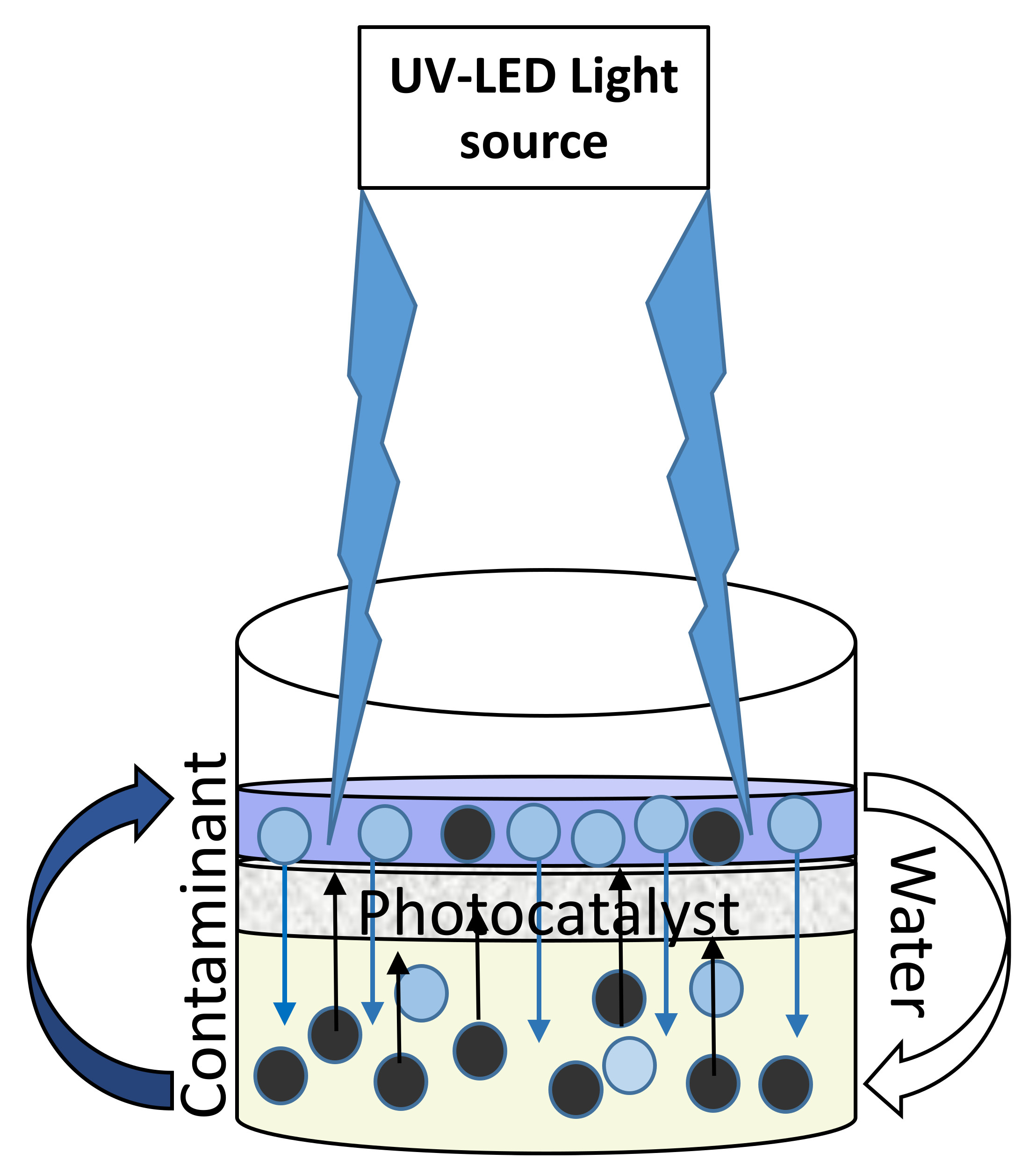
The irradiation source was an ultraviolet – light-emitting diode (UV-LED) panel. UV-LEDs were selected for their energy efficiency and longer lifespan compared to low-pressure UV lamps (i.e., approximately four times) [6,49,50]. Additionally, LEDs contain no mercury, making them an environmentally friendly alternative to standard fluorescent UV bulbs.
The experiments were conducted in a semi-passive mode, where no mixing was involved during the irradiation. The objective was to investigate what can be expected of a semi-passive photocatalytic system if it was to be used to treat ponds containing contaminated water under an ambient environment. Thereby, the reaction rates can be representative of the rate of removal of organic contaminants in natural contaminated watersheds and industrial wastewater ponds that are exposed to sunlight.
2. Materials and Methods
2.1. Materials
The titanium mesh with 99.9% purity was supplied from Alfa Aesar. The titanium plate with 99.7% purity was obtained from Sigma-Aldrich, St. Louis, MO, USA. The 6061-grade aluminum was used as a cathode for anodization and was procured from New West Metals Inc., Winnipeg, MB, Canada. The hollow glass microspheres coated with anatase TiO2 (HGMT) were obtained from Cospheric Innovations in Microtechnology. They are referred to as photospheres in this paper and had a median diameter of 45 µm and density of 0.22 g/cm3.
A 99% pure-ethylene glycol was supplied by VWR and 99.9% pure acetone was obtained from EMD. A 98% pure ammonium fluoride, 99.8% ethyl acetate and 99.8% methanol were obtained from Sigma-Aldrich. The phosphoric acid was supplied by J. T. Baker. Commercially available Killex® containing 95 g/L of 2,4-dichlorophenoxyacetic acid (2,4-D), 52.5 g/L of Mecoprop-P, and 9 g/L of Dicamba was purchased from a local retailer.
An in-house UV-LED light source (λ = 365 nm) composed of 16 lamps (NSCU330B, Nichia Corporation, Anan, Japan) in a four by four array on a 10 cm by 10 cm circuit board was used as a light source. It was equipped with an air fan to cool down the generated heat from the lamps. A dual output power supply (Model TW 5005D) was used to drive the module with direct current, ranging from 10 mA to 500 mA [51]. A PANalytical Aeris X-ray diffractometer was used for X-ray diffraction (XRD) characterization of the photocatalysts. The HighScore Plus XRD analysis software was utilized for Qualitative XRD analysis and Rietveld Refinement. An SEM (JEOL JSM-IT300LV, Tokyo, Japan) by InTouchScope and a TEM (Tecnai F20, by Thermo Fischer Scientific) were used to characterize the morphologies of the anodized titanium mesh. A Hummer II sputter coater from Anatech, USA was used to coat the cathode (anodized titanium mesh) with platinum.
2.2. Methods
2.2.1. Experimental Design and Setup
All experiments were conducted at room temperature, pressure, and under similar conditions. In order to be able to compare the photocatalyst supports (as a variable), all experimental parameters including light source, irradiation light intensity, lack of mixing, distance from the light source and the initial concentration of 2,4-D in the solution were identical in all experiments. The type of the photocatalyst support was different in each experiment, therefore the performance of the studied photocatalysts (i.e., TiO2 photospheres, anodized titanium mesh, plate and electro-photocatalysis using an anodized titanium mesh) were studied as a variable.
The output light intensity of the UV-LED module was linear in the range of 2.2 mW/cm2 to 17.3 mW/cm2. The light intensity was adjusted at 15 mW/cm2 [51]. The distance of the photocatalyst surface from the irradiation source was 5.5 cm in all experiments.
Wide mounted glass jars with a diameter of 4 cm were used as reaction vessels. In all experiments, 0.52 mL of Killex® was dissolved in 1 L of milli-Q water resulting in a solution containing 49.4 ppm 2,4-D, 27.3 ppm Mecoprop-P and 4.68 ppm Dicamba. In each experiment, a control sample without a photocatalyst was also monitored to evaluate the possible photolysis in the solutions. The length of time between sampling intervals created a requirement to correct the mass of the solution for evaporation. This was done by monitoring the mass of the solution during the experiments. The milli-Q water was added before each sampling to adjust the mass of the solution to its initial mass before each irradiation cycle.
In the experiments using an anodized titanium plate, the plate was placed at the bottom of the reaction jar. Dimensions of the plate were measured and used to calculate the surface area of the photocatalyst for energy calculations. When the titanium mesh was used, it was secured close to the surface of the reaction medium using a stainless steel wire mesh. The surface area of the mesh was calculated based on its dimensions and the percentage of the open area (64%) was used to calculate the effective surface area for energy calculations.
In the electro-photocatalysis experiments, a platinum coated anodized mesh was used as a cathode, and the anodized titanium mesh was used as a photoanode. Anode and cathode were connected to a battery (1.5 V) as a source of direct electric current. Current and voltage were measured with a voltmeter and ammeter during the experiment.
For the TiO2 photospheres experiments, the photospheres were mixed with water and those that were buoyant, were collected and dried overnight. The photospheres were then mixed with spiked water using a magnetic stirrer for 30 min before irradiation to allow adsorption to reach equilibrium. In order to identify an optimum photocatalyst loading for the purpose of comparison with the other studied photocatalysts, three different catalyst loadings were tested, 7.2 mg/cm2 and 11.9 mg/cm2 and 16.7 mg/cm2, equal to 1.8 g/L, 3.0 g/L, and 4.2 g/L, respectively. Since the photocatalyst was floating on the surface, the surface area of the reaction jar was considered as the irradiated surface by the light source and was used in energy calculations.
2.2.2. Anodization of Titanium Mesh
Supported TiO2 nanotubes were prepared by anodization of a titanium mesh followed by a temperature controlled annealing to acquire anatase phase, which is the most desired crystalline morphology of TiO2 for photocatalytic applications [52]. The titanium mesh was first degreased by sonication in an acetone/methanol solution for 30 min. It was then rinsed with water and dried at room temperature. The degreased mesh was anodized in an aqueous solution of ethylene glycol, containing 2% water and 0.5% ammonium fluoride for 24 h. The anodized mesh was then rinsed with water and dried at room temperature followed by annealing in the oven for 3 h at 450 °C to form an anatase crystalline structure [24,26,45,46,47]. The mesh was cut into uniform pieces with a surface area of 2.9 ± 0.3 cm2, and each of them were attached to a reaction jar via a stainless steel wire and irradiated under the UV-LED lamp.
2.2.3. Sample Analysis
Samples were filtered using 0.45 µm PTFE 25 mm syringe filters before analysis, and were analyzed using HPLC with a UV-visible detector, fitted with a Restek Pinnacle DB C18 column. Absorbance was recorded at a wavelength of 230 nm. Ingredients of Killex®, have all the peak wavelength at the range of 230 nm to 280 nm (i.e., 2,4-D: λmax = 280 nm, Mecoprop: λmax = 230 nm and Dicamba: λmax = 275 nm) [6,53,54]. The UV detection wavelength of 230 nm is selected so as to be able to detect all three compounds in the Killex® solution [55]. However, degradation of 2,4-D as a model contaminant is studied in this paper for the purpose of comparison of the photocatalysts. The eluent used was water:methanol (25:75) with ten mM phosphoric acid and a flow rate of 1 L/min.
3. Results and Discussion
3.1. Photocatalyst Characterization
Titanium dioxide exists in three different crystalline structures of rutile, anatase and brookite [56]. The anatase and rutile show different structural characteristics in terms of Ti–Ti and Ti–O distances. The Ti–Ti distance is larger in anatase than rutile but the Ti–O distance is shorter. These structural differences lead to different mass densities and different electronic structures that causes the difference in the mobility of the charge carriers under light excitation [57]. Amongst all crystal structures of TiO2, the anatase shows the highest photocatalytic activity [56]. The X-ray diffractometry (XRD) of the photocatalysts indicated that the primary crystal structure of all the photocatalysts was anatase. (The XRD graphs of all the photocatalyst samples are presented in the supplementary material).
The XRD quantitative results that show the weight percentage of titanium, TiO2, and its crystalline morphologies are presented in Table 1.
Further analysis was performed on the mesh photocatalyst for characterizing the surface morphology, length, and thickness of the nanostructures by a scanning electron microscope (SEM) and a transmission electron microscope (TEM). Images are presented in Figure 1. As it can be seen on the images, the length of the nanotubes was about 300 nm with the opening diameter of 54 nm.
3.2. TiO2 Photospheres
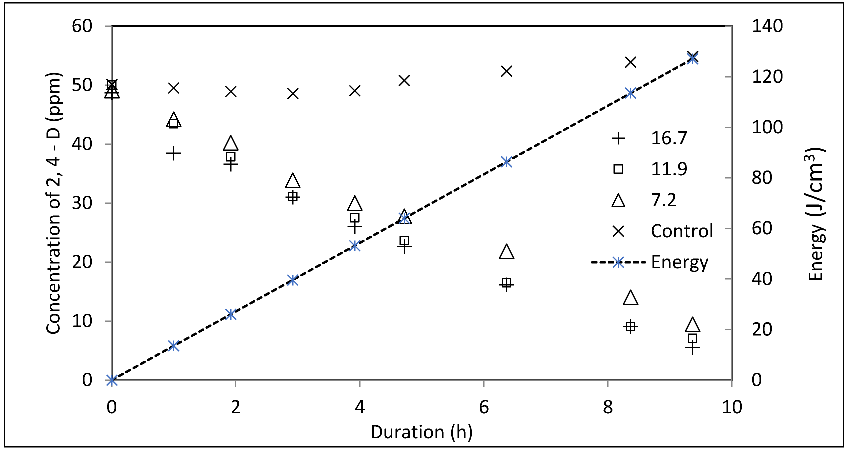
A comparative study of the photosphere loadings was conducted. The results are presented in Figure 2. Samples were irradiated for nine h and 22 min with a total energy of 127.1 J/cm3. The 2,4-D has no absorbance at the peak wavelength of LED (λ = 365 nm). Therefore, no direct photolysis took place during its degradation [6]. The degradation showed a notable improvement when increased beyond a photosphere loading of 7.2 mg/cm2, while results of 11.9 mg/cm2 and 16.7 mg/cm2 were similar. The degradation by photospheres in this study followed a zero-order reaction kinetics, with the kinetic rate constant (K value) of 4.12 mg L−1 h−1 and the half-life time of 6.05 h at a loading of 7.2 mg/cm2. K values were 4.55 mg L−1 h−1 and 4.36 mg L−1 h−1, and the half-life times were 5.48 h and 5.72 h at the two higher loadings of 11.9 mg/cm2 and 16.7 mg/cm2 respectively. No degradation took place in the control sample. Zero-order reaction kinetics was also reported in other studies, where TiO2 floating beads were used for the degradation of dyes [36]. The degradation efficiency was 80%, 86% and 89% at the loadings of 7.2 mg/cm2, 11.9 mg/cm2 and 16.7 mg/cm2 respectively. The results are summarized in Table 2.
The results indicated that increasing the loading of photospheres in the solution increased the degradation rate up to an optimum value beyond which the degradation rate decreased as more photocatalyst was added. This phenomenon has been demonstrated by various researchers [58]. Since heterogeneous photocatalysis occurs inside the active sites on the surface of TiO2, the rate of degradation increases when the loading of the photocatalyst increases. This is due to the higher surface area, hence the availability of the active reaction sites. However, an optimum TiO2 dosage exists after which degradation rates will decrease with higher catalyst loadings [59]. This phenomenon has been attributed to photon limitation or light scattering on the surface of the photocatalyst particles, decreased light penetration through active sites, and uneven competition between the nanoparticles for light adsorption at higher loadings [60]. Moreover, the high catalyst loading may deactivate the originally activated TiO2 through collision with ground state catalysts. The following reaction demonstrates the collision mechanism between TiO2 species. has the activated species adsorbed on its surface, TiO2 is the ground state and is the deactivated state of TiO2 [61,62]. When the light activated collides with the ground state TiO2, gets deactivated (), leaving the ground state behind. A high loading of the photocatalyst, increases the chance of collision between the species, resulting in the higher frequency in the deactivation process.
A screening effect of UV irradiation is also reported to be responsible for lowering the rate of photocatalysis at the loading values beyond the threshold limit [59,63]. In addition, due to the uncontrolled catalyst agglomeration on the sidewalls of the reaction jar, increasing the catalyst loading does not enhance the available catalyst on the surface of the reaction media. Since most of the studies utilize photospheres in a reactor with mixing, this phenomenon is fairly reported in the literature [9,64].
The experiments resulted in similar degradation rates in two photocatalyst loadings. Therefore, it is possible that the optimum level of loading was reached. This allows for a comparison to other suspended photocatalytic methods as the measured level of treatment represents the highest level of attainable degradation by photospheres.
3.3. Anodized Mesh
An experimental study utilizing the anodized TiO2 mesh was performed to assess its photocatalytic activity in a semi-passive mode, and as well to compare it with the anodized plate and other methods studied here. The degradation of 2,4-D with time is presented in Figure 3. The zero-order kinetic rate constant was 3.45 mg L−1 h−1 with the half-life time (t1/2) of 7.09 h. Energy consumption to achieve 99.8% degradation was on average 160 J/cm3.
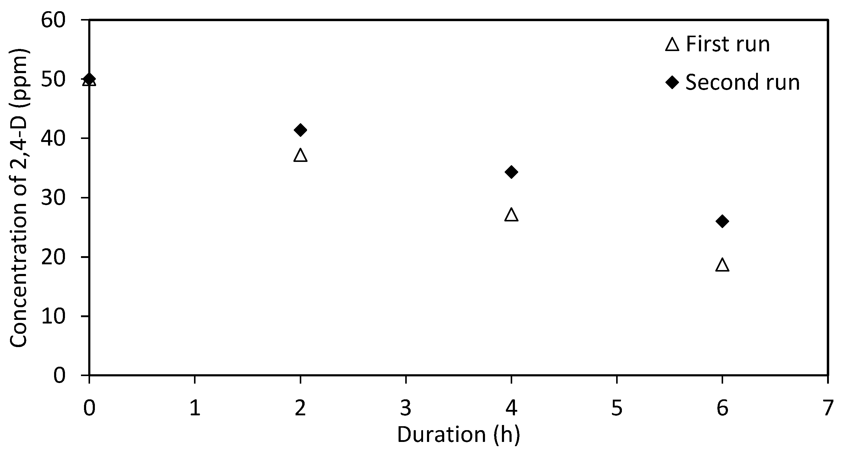
Experiments were performed in duplicate to account for considerable variances that can occur when growing TiO2 nanotubes on the non-uniform surface of the mesh. The degradation efficiency varied 2.2% between the replicate samples. Although the percentage was small, the difference between samples can be attributed to the variation on nanotube structure due to the variations in the electrical field alongside the wires of the mesh during the anodization process. This emphasizes the importance of the production of a uniform mesh.
Each TiO2 mesh was tested a second time to assess its durability in repeated applications. One of the samples showed a similar efficiency with degradation efficiency varied between 99.65 to 100%, but the degradation efficiency dropped 13% in the second replicate. The decreased efficiency has been reported for repeated runs on TiO2 nanotube meshes by Liao et al. [26], who found that after five runs the degradation efficiency decreased by 8%. The mechanism for loss of degradation efficiency is due to the imperfect mechanical stability of the nanotube layers as TiO2 nanotubes tend to flake off from the substrate during the experiment [65]. Previous research [66] showed that the mechanical stability of TiO2 nanotube arrays could be improved by surface modification methods such as incorporating carbon into microstructures of nanotube layers, which increases the hardness and mechanical strength of the layers. In another study, it was demonstrated that the presence of fluoride-rich layer improves the adhesion of the nanotube layer [65].
Variables affecting anodization are electrolytes types, voltage, and duration of the anodization, annealing temperature and duration, as well as the distance between the electrodes. They cause a difference in the crystal phase, length and width of the produced TiO2 nanotubes which is the reason behind the difference in their mechanical stability on the surface of the titanium mesh [25,26,28,67,68,69,70]. When the nanotubes are not mechanically stable, they can fall off from the surface in repetitive usage, resulting in a reduced photocatalytic activity.
3.4. Anodized Plate
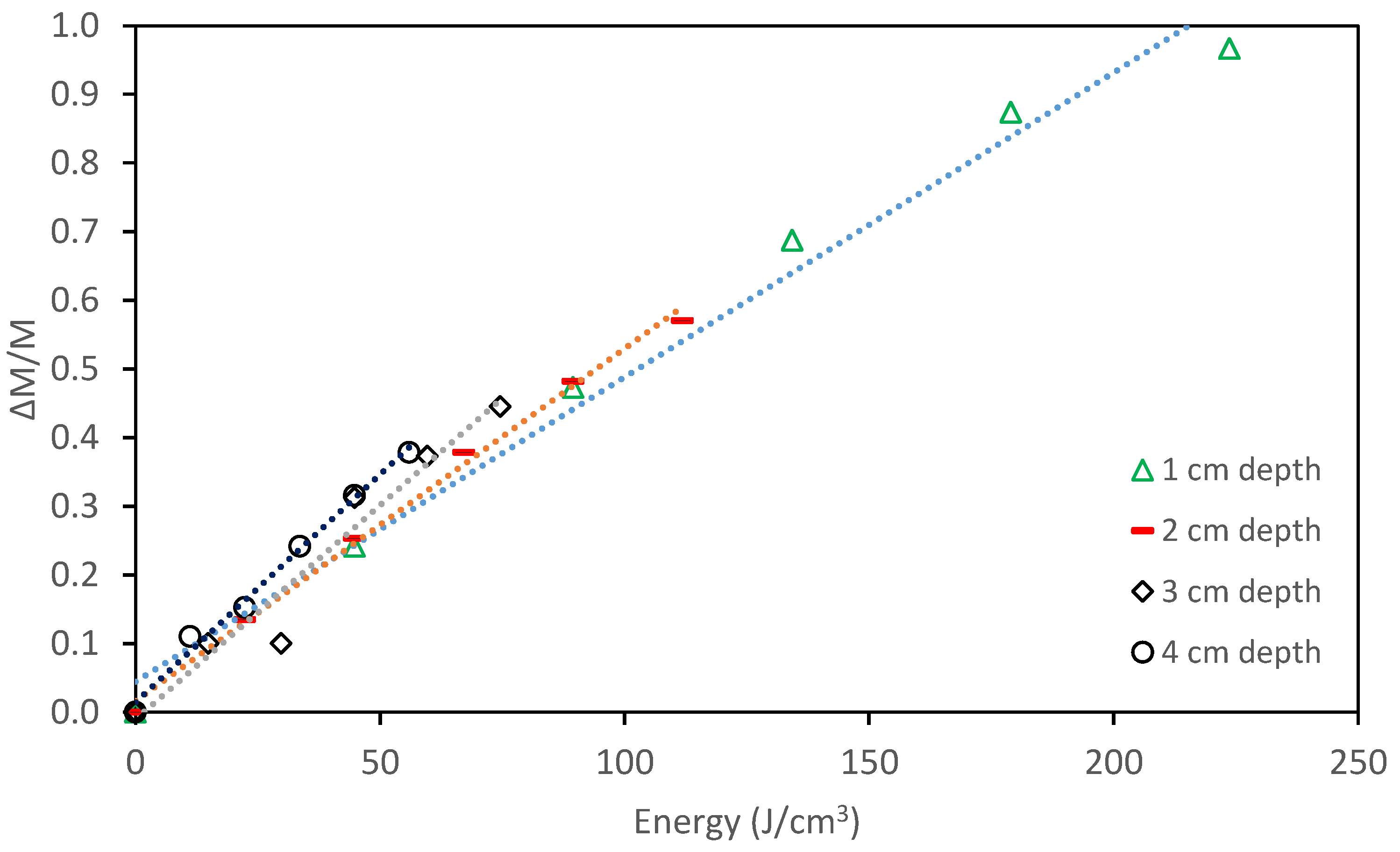
The degradation efficiency was 57% after 10 h of irradiation, consuming 111.9 J/cm3 of energy. Degradation followed a zero-order degradation rate constant of 3.07 mg L−1 h−1 with the half-life time of 7.97 h. Since the photocatalyst plate was placed at the bottom of the reaction jar, an additional experiment was performed to investigate the effect of the depth of water column on the degradation efficiency. The plate was covered with contaminated water, which resulted in various water depths ranging from 1 cm to 4 cm on top of the photocatalyst plate. The concentration, distance from the irradiation source and the light intensity were identical in all samples. All samples irradiated for 10 h. The results are presented in Figure 4.
It was observed that at a depth of 4 cm, energy consumption was 55.9 J/cm3 to achieve 38% degradation efficiency (defined as ΔM/M0 = (M0 − Mt)/M0), which was 27% lower compared to a 1 cm depth (76.3 J/cm3). The results showed that the increase in depth, did not decrease the energy efficiency of the system. Although the Beer Lambert equation (A = ε b c) states light absorbance in a solution (A) is directly proportional to its path length (b), molar concentration (c), and molar absorptivity (ε), the results showed that the effect of path length at the studied depth ranging from 1 cm to 4 cm was negligible.
This could be associated with the mass of the contaminant which is a significant parameter in the photocatalytic degradation reactions due to its effect on the adsorption of the reactant on the surface of the photocatalyst and mass transfer in the solution during the photocatalytic degradation reaction [9,71,72]. Since the mass was higher when the water column was higher, the effect of mass supersedes the effect of light absorbance between the studied depths of 1 to 4 cm. It was then concluded that when the anodized plate is placed at the bottom of the reaction jar, the effect of the depth of water column is not as important as the mass of the contaminant; hence it can be neglected. Therefore, the results are comparable with the floating photospheres and mesh, where the photocatalyst is brought near the surface.
3.5. Electro-Photo Catalysis Using Anodized Titanium Mesh
A study for comparative analysis of electro-photocatalysis was conducted on the anodized TiO2 mesh. Voltage, as the driving force in preventing electron-hole pair recombination [39], was kept constant at 1.5 ± 0.1 V during the 6 h irradiation. The photocurrent increased from 6 mA before irradiation to about 40 mA after UV irradiation. Voltage was variable at the first 20 min which was corrected by manually adjusting to the initial value of 1.5 V. The current was approximately 45 mA during the 6 h irradiation period. Results of the experiment are presented in Figure 5.
Kinetics followed a zero-order model with a rate constant of 5.04 mg L−1 h−1 with the half-life time of 4.86 h during the first run. The enhanced degradation efficiency is due to the presence of the polarized anode, working as a photoanode in the photoelectrochemical cell. The applied voltage produced an electric field which is opposed to the attraction forces between excited electrons and the holes that are produced during photocatalysis. This results in excited electrons being removed from the surface of TiO2, minimizing the electron–hole recombination [39,40,41,73]. The same mesh was tested a second time, showing an efficiency drop of 14% compared to the initial run. Literature on the loss of degradation efficiency varies considerably. It was reported from no loss [41] to 7% [74] and 8% [26] efficiency reduction during the repeated cycles. The mechanism for the reduction in the photocatalytic activity after repeated use is the same as discussed for TiO2 mesh earlier.
3.6. Comparison of Three Forms of the Photocatalyst and Electro-Photocatalysis
The required energy to achieve 60% degradation was used to compare the efficiency of the four studied photocatalysts. In the experiments using the mesh photocatalyst, the average value of the energy consumption of the four experiments is used for the purpose of comparison.
Energy (Elamp in J/cm3) was calculated based on the LED output in mW/cm2 and the surface area of the photocatalyst. Therefore, the variation of the surface area of the different photocatalysts was taken into account. The degradation efficiency or the normalized degraded mass of 2,4-D (∆M) was calculated based on the mass difference during the photocatalytic reaction using the following equation where M0 is the initial mass of 2,4-D in the solution, and Mt is its mass at various sampling intervals:
In electro-photocatalysis, the applied excessive voltage was accounted in energy calculations. The following equations were used to calculate the total consumed energy per volume of the sample (Etotal in J/cm3):
where V is the average potential of the electrochemical cell (in V), I is the average of measured current during irradiation (in A), t is time (in s) and Vs is the volume of the solution (in cm3) [75,76]. The results are summarized in Table 3, and illustrated in Figure 6.
It was observed that energy consumption was at the same level in the anodized plate (i.e., 114.5 J/cm3) and electro-photocatalysis (i.e., 112.2 J/cm3). Energy consumption was also similar in the photospheres experiment at 80.3 J/cm3, with the average energy consumption of the four studied anodized mesh at 80.3 J/cm3. In comparison to the photospheres experiment and the mesh, energy consumption was 39% higher on average when the anodized plate and electro-photocatalysis were used.
The lower efficiency and higher energy consumption of the anodized plate is due to the 2D geometry of its planar surface compared to the 3D nanostructures on the mesh [26]. Although the dimensions of the plate and mesh were similar, void spaces in the mesh resulted in a significantly lower surface area available for light absorbance. In contrast, the three-dimensional surface morphology of TiO2 nanotubes grown on a mesh are more efficient in the absorbance of the scattered light compared to the 2D geometry of the planar surface of the titanium plate despite having a lower surface available for irradiation. Moreover, the interstitial fissures between the nanotubes allow contaminant molecules easier access to the photocatalyst surface area, which enhances the photocatalytic activity.
This phenomenon has been studied by other researchers [26] in the photocatalytic degradation of methyl orange under a high-pressure mercury lamp with the wavelength of 365 nm. It was demonstrated that under similar conditions and equal time (360 min), the photocatalytic degradation of methyl orange was 18% higher when an anodized mesh was compared with an anodized plate.
The outperformance of the photospheres in comparison to the plate can be attributed to the increased access to the catalyst surface area by photons and the reactants—a primary factor in determining the degradation rate in photocatalysis. Other studies have also demonstrated similar results [51].
It was observed that with a similar amount of energy, the degradation efficiency of the anodized mesh was comparable with photospheres. This is due to the improved photocatalytic activity of the supported TNTs and 3D structures of TiO2 surrounding the mesh wires, compared to anatase TiO2, mounted on the glass spheres. Moreover, it has significant advantages because a separation step after treatment is not required, and it can be removed easily when the treatment is completed.
Albeit electro-photocatalysis resulted in the lowest half-life time (i.e., 4.86 h) compared to the methods studied here, but its energy consumption was at the same level as the anodized plate. This outcome was also in-line with other published comparative studies [41,42,75,76,77]. The enhanced efficiency is attributed to the presence of the electrical bias between the electrodes which minimized the electron-hole recombination on the photocatalyst and increased the quantum yield of the photocatalytic degradation process. The primary disadvantage of this system is the required additional electricity to the photoanode as well as the increased complexity of the process, which leads to a higher capital and operational costs [75].
The studied semi-passive system using the anodized plate is also compared with a flow-through photoreactor, using the same anodized plate and the same light source to degrade 2,4-D in a Killex® solution [49]. During 2 h of irradiation, the photoreactor resulted in 78% higher degradation efficiency of = 0.25 compared to = 0.14 in the semi-passive system. Energy consumption of the semi-passive system was 44.8 J/cm3 at = 0.25 which was 3.6 times higher than the photoreactor (12.5 J/cm3). This difference is due to the slower kinetics of the photocatalytic degradation in the semi-passive system due to the lack of mixing that minimizes mass transfer. The reported pseudo first-order kinetic rate constant was 648 h−1 in the reactor, compared to the zero-order rate constant of 3.07 mg L−1 h−1 in the semi-passive photocatalysis. It can be concluded that the semi-passive photocatalysis consumes more energy and results in a lower degradation efficiency during a same period of time when compared to a photoreactor.
Although photospheres have recently been broadly and successfully studied for degradation of environmental contaminants [20,78,79,80,81], their usage is still constrained by problems with separation after treatment. Moreover, ensuring the even dispersion of the photospheres for a semi-passive treatment, with no mixing, may be a challenge in practical applications. Furthermore, a direct comparison between the publications in this field and the results presented in this paper is not feasible due to the different operational parameters and the variety of the studied contaminants. The feasibility of utilization of the robust anodized TiO2 based photocatalysts, designing a system for field applications at a larger scale, and studying the system to degrade various organic contaminants in water will be the direction for future research.
4. Conclusions
- The feasibility of using four types of TiO2 photocatalysts under UV-LED irradiation (i.e., λ = 365 nm) in a semi-passive system was investigated.
- Energy consumption (J/cm3) was used to rank the degradation efficiency of the photocatalysts. Photospheres (80.3 J/cm3) and anodized titanium mesh (80.3 J/cm3) showed similar efficiencies followed by electro-photocatalysis (112.2 J/cm3) and the anodized plate (114.5 J/cm3).
- Although the electro-photocatalysis rate of reaction was 64% higher than the photocatalysis with anodized plates, and 46% higher than the photocatalysis using the anodized mesh, it required additional energy and control during the photocatalytic degradation process.
- Increasing the loadings of the photospheres enhanced the kinetics of the degradation reaction from 4.12 mg L−1 h−1 to 4.55 mg L−1 h−1, but further increases in the loadings reduced the rate of reaction to 4.36 mg L−1 h−1. The variation in the rate of reaction, validated the deactivation of the originally activated species of TiO2 due to the collision mechanism and the UV screening effect.
- Though the degradation rate and efficiency was high with photospheres, they still would require a separation step after treatment. This minimizes their attractiveness for application under ambient environments.
- Studying the depth of the photocatalyst from the surface showed at the range of 1 cm to 4 cm, the effect of the mass of the contaminant in the solution supersedes the effect of the light penetration.
- Anodized mesh showed 29% higher efficiency with 56% surface area of the anodized plate, but its performance varied during repetitive usage. The resulted variation is associated with the ability of the anodization process to generate a uniform mesh with a stable photocatalyst on its surface. This emphasizes the importance of improving the anodization process to produce a robust and uniform mesh which will be considered in future studies.
Supplementary Materials
The following are available online at https://www.mdpi.com/2073-4441/11/3/621/s1, Figure S1. XRD of titanium dioxide mesh, Figure S2. XRD of titanium dioxide plate, Figure S3. XRD of titanium dioxide photospheres.
Author Contributions
G.H. designed the study and conducted the experiments, analyzed data and wrote the original draft of the paper; J.H. edited the paper and supported data analysis; G.A. oversaw the research and contributed in experimental design, data analysis and reviewed the final draft; Late C.H.L. oversaw the research and experimental design. He could not review this manuscript.
Funding
This research was partially funded by CMC Research Institutes, MITACS and Natural Sciences and Engineering Research Council of Canada (NSERC).
Acknowledgments
The authors would like to thank Mitacs, and CMC Research Institutes and Natural Sciences and Engineering Research Council of Canada (NSERC) for providing partial funding for the project.
Conflicts of Interest
The authors declare no conflict of interest. The funders had no role in the design of the study; in the collection, analyses, or interpretation of data; in the writing of the manuscript, and in the decision to publish the results.
References
- Fujishima, A.; Honda, K. Electrochemical evidence for the mechanism of the primary state of photosynthesis. Bull. Chem. Soc. Jpn. 1971, 44, 1148–1150. [Google Scholar] [CrossRef]
- Mondal, K. Recent advances in the synthesis of metal oxide nanofibers and their environmental remediation applications. Inventions 2017, 2, 9. [Google Scholar] [CrossRef]
- Chong, M.N.; Jin, B.; Chow, C.W.K.; Saint, C. Recent developments in photocatalytic water treatment technology: A review. Water Res. 2010, 44, 2997–3027. [Google Scholar] [CrossRef]
- Wang, C.; Liu, H.; Qu, Y. TiO2-based photocatalytic process for purification of polluted water: Bridging fundamentals to applications. J. Nanomater. 2013, 2013, 319637. [Google Scholar] [CrossRef]
- Toor, A.P.; Verma, A.; Jotshi, C.K.; Bajpai, P.K.; Singh, V. Photocatalytic degradation of 3, 4-dichlorophenol using TiO2 in a shallow pond slurry reactor. Indian J. Chem. Technol. 2005, 12, 75–81. [Google Scholar]
- Yu, L.; Achari, G.; Langford, C.H. LED-based photocatalytic treatment of pesticides and chlorophenols. J. Environ. Eng. 2013, 139, 1146–1151. [Google Scholar] [CrossRef]
- Ikehata, K.; El-Din, M.G.; Snyder, S.A. Ozonation and advanced oxidation treatment of emerging organic pollutants in water and wastewater. Ozone Sci. Eng. 2008, 30, 21–26. [Google Scholar] [CrossRef]
- Augugliaro, V.; Bellardita, M.; Loddo, V.; Palmisano, G.; Palmisano, L.; Yurdakal, S. Overview on oxidation mechanisms of organic compounds by TiO2 in heterogeneous photocatalysis. J. Photochem. Photobiol. C Photochem. Rev. 2012, 13, 224–245. [Google Scholar] [CrossRef]
- Pelaez, M.; Nolan, N.T.; Pillai, S.C.; Seery, M.K.; Falaras, P.; Kontos, A.G.; Dunlop, P.S.M.; Hamilton, J.W.J.; Byrne, J.A.; O’Shea, K.; et al. A review on the visible light active titanium dioxide photocatalysts for environmental applications. Appl. Catal. B Environ. 2012, 125, 331–349. [Google Scholar] [CrossRef] [Green Version]
- Blake, D.M. Bibliography of work on the heterogeneous photocatalytic removal of hazardous compounds from water and air. Natl. Renew. Energy Lab. 2001, 4, 1–265. [Google Scholar] [CrossRef]
- Zhang, B.; Cao, S.; Du, M.; Ye, X.; Wang, Y.; Ye, J. Titanium Dioxide (TiO2) Mesocrystals: Synthesis, Growth Mechanisms and Photocatalytic Properties. Catalysis 2019, 9, 91. [Google Scholar] [CrossRef]
- Fagan, R.; McCormack, D.E.; Dionysiou, D.D.; Pillai, S.C. A review of solar and visible light active TiO2 photocatalysis for treating bacteria, cyanotoxins and contaminants of emerging concern. Mater. Sci. Semicond. Process. 2015, 42, 2–14. [Google Scholar] [CrossRef]
- Lavand, A.B.; Malghe, Y.S. Visible light photocatalytic degradation of 4-chlorophenol using C/ZnO/CdS nanocomposite. J. Saudi Chem. Soc. 2015, 19, 471–478. [Google Scholar] [CrossRef] [Green Version]
- Huang, Z.F.; Song, J.; Pan, L.; Zhang, X.; Wang, L.; Zou, J.J. Tungsten oxides for photocatalysis, electrochemistry, and phototherapy. Adv. Mater. 2015, 27, 5309–5327. [Google Scholar] [CrossRef] [PubMed]
- Zheng, H.; Ou, J.Z.; Strano, M.S.; Kaner, R.B.; Mitchell, A.; Kalantar-Zadeh, K. Nanostructured tungsten oxide–properties, synthesis, and applications. Adv. Funct. Mater. 2011, 21, 2175–2196. [Google Scholar] [CrossRef]
- Smith, Y.R.; Sarma, B.; Mohanty, S.K.; Misra, M. Light-assisted anodized TiO2 nanotube arrays. ACS Appl. Mater. Interfaces 2012, 4, 5883–5890. [Google Scholar] [CrossRef] [PubMed]
- Heller, A.; Brock, J. Materials and Methods for Photocatalyzing Oxidation of Organic Compounds on Water. U.S. Patent 4,997,576, 5 March 1991. Available online: http://www.freepatentsonline.com/4997576.html (accessed on 26 March 2019).
- Gjipalaj, J.; Alessandri, I. Easy recovery, mechanical stability, enhanced adsorption capacity and recyclability of alginate-based TiO2 macrobead photocatalysts for water treatment. J. Environ. Chem. Eng. 2017, 5, 1763–1770. [Google Scholar] [CrossRef]
- Robert, D.; Keller, V.; Keller, N. Immobilization of a semi-conductor photocatalyst on solid supports, methods, materials and applications. In Photocatalysis and Water Purification: From Fundamentals to Recent Applications; Lu, M., Pichat, P., Eds.; John Wiley & Sons, Incorporated: Hoboken, NJ, USA, 2013; pp. 145–172. ISBN 9783527645411. [Google Scholar]
- Abdel-Maksoud, Y.; Imam, E.; Ramadan, A. TiO2 solar photocatalytic reactor systems: Selection of reactor design for scale-up and commercialization—Analytical review. Catalysts 2016, 6, 138. [Google Scholar] [CrossRef]
- Sakthivel, S.; Shankar, M.V.; Palanichamy, M.; Arabindoo, B.; Murugesan, V. Photocatalytic decomposition of leather dye comparative study of TiO2 supported on alumina and glass beads. J. Photochem. Photobiol. A Chem. 2002, 148, 153–159. [Google Scholar] [CrossRef]
- Sirisuk, A.; Hill, C.G.; Anderson, M.A. Photocatalytic degradation of ethylene over thin films of titania supported on glass rings. Catal. Today 1999, 54, 159–164. [Google Scholar] [CrossRef]
- Portjanskaja, E.; Krichevskaya, M.; Preis, S.; Kallas, J. Photocatalytic oxidation of humic substances with TiO2-coated glass micro-spheres. Environ. Chem. Lett. 2004, 2, 123–127. [Google Scholar] [CrossRef]
- Ge, M.; Cao, C.; Huang, J.; Li, S.; Chen, Z.; Zhang, K.-Q.; Al-Deyab, S.S.; Lai, Y. A review of one-dimensional TiO2 nanostructured materials for environmental and energy applications. J. Mater. Chem. A 2016, 4, 6772–6801. [Google Scholar] [CrossRef]
- Zeng, Q.; Xi, M.; Xu, W.; Li, X. Preparation of titanium dioxide nanotube arrays on titanium mesh by anodization in (NH4)2SO4/NH4F electrolyte. Mater. Corros. 2013, 64, 1001–1006. [Google Scholar] [CrossRef]
- Liao, J.; Lin, S.; Zhang, L.; Pan, N.; Cao, X.; Li, J. Photocatalytic degradation of methyl orange using a TiO2/Ti mesh electrode with 3D nanotube arrays. ACS Appl. Mater. Interfaces 2012, 4, 171–177. [Google Scholar] [CrossRef]
- Roy, P.; Berger, S.; Schmuki, P. TiO2 nanotubes: Synthesis and applications. Angew. Chem.–Int. Ed. 2011, 50, 2904–2939. [Google Scholar] [CrossRef]
- Jun, Y.; Park, J.H.; Kang, M.G. The preparation of highly ordered TiO2 nanotube arrays by an anodization method and their applications. Chem. Commun. 2012, 48, 6456–6471. [Google Scholar] [CrossRef]
- Albu, S.P.; Ghicov, A.; Macak, J.M.; Hahn, R.; Schmuki, P. Self-organized, free-standing TiO2 nanotube membrane for flow-through photocatalytic applications. Nano Lett. 2007, 7, 1286–1289. [Google Scholar] [CrossRef]
- Motola, M.; Satrapinskyy, L.; Roch, T.; Šubrt, J.; Kupčík, J.; Klementová, M.; Jakubičková, M.; Peterka, F.; Plesch, G. Anatase TiO2 nanotube arrays and titania films on titanium mesh for photocatalytic NOXremoval and water cleaning. Catal. Today 2017, 287, 59–64. [Google Scholar] [CrossRef]
- Zhong, M.; Zhang, G.; Yang, X. Preparation of Ti mesh supported WO3/TiO2 nanotubes composite and its application for photocatalytic degradation under visible light. Mater. Lett. 2015, 145, 216–218. [Google Scholar] [CrossRef]
- Cunha, D.L.; Kuznetsov, A.; Achete, C.A.; da Hora Machado, A.E.; Marques, M. Immobilized TiO2 on glass spheres applied to heterogeneous photocatalysis: Photoactivity, leaching and regeneration process. PeerJ. 2018, 4464, 1–19. [Google Scholar] [CrossRef] [PubMed]
- Hartley, A.C.; Moss, J.B.; Keesling, K.J.; Moore, N.J.; Glover, J.D.; Boyd, J.E. PMMA-titania floating macrospheres for the photocatalytic remediation of agro-pharmaceutical wastewater. Water Sci. Technol. 2017, 75, 1362–1369. [Google Scholar] [CrossRef]
- Xing, Z.; Li, J.; Wang, Q.; Zhou, W.; Tian, G.; Pan, K.; Tian, C.; Zou, J.; Fu, H. A floating porous crystalline TiO2 ceramic with enhanced photocatalytic performance for wastewater decontamination. Eur. J. Inorg. Chem. 2013, 2411–2417. [Google Scholar] [CrossRef]
- Magalhães, F.; Moura, F.C.C.; Lago, R.M. TiO2/LDPE composites: A new floating photocatalyst for solar degradation of organic contaminants. Desalination 2011, 276, 266–271. [Google Scholar] [CrossRef]
- Magalhães, F.; Lago, R.M. Floating photocatalysts based on TiO2 grafted on expanded polystyrene beads for the solar degradation of dyes. Sol. Energy 2009, 83, 1521–1526. [Google Scholar] [CrossRef]
- Bahreini, Z.; Heydari, V.; Hekmat, A.N.; Taheri, M.; Vahid, B.; Moradkhannejhad, L. A comparative study of photocatalytic degradation and mineralisation of an azo dye using supported and suspended nano-TiO2 under UV and sunlight irradiations. Pigment Resin Technol. 2016, 45, 119–125. [Google Scholar] [CrossRef]
- Salinaro, A.; Emeline, A.V.; Zhao, J.; Hidaka, H.; Ryabchuk, V.K.; Serpone, N. Terminology, relative photonic efficiencies and quantum yields in heterogeneous photocatalysis. Part I: Suggested protocol. Pure Appl. Chem. 1999, 71, 303–320. [Google Scholar] [CrossRef]
- Turolla, A. Heterogeneous Photocatalysis and Electro-Photocatalysis on Nanostructured Titanium Dioxide for Water and Wastewater Treatment: Process Assessment, Modelling and Optimization. Ph.D. Thesis, Polytechnic University of Milan, Milan, Italy, 2014. [Google Scholar]
- Zlamal, M.; Macak, J.M.; Schumulu, P.; Josef, K. Electrochemically assisted photocatalysis on self-organized TiO2 nanotubes. Electrochem. Commun. 2007, 9, 2822–2826. [Google Scholar] [CrossRef]
- Turolla, A.; Fumagalli, M.; Bestetti, M.; Antonelli, M. Electro-photocatalytic decolorization of an azo dye on TiO2 self-organized nanotubes in a laboratory scale reactor. Desalination 2012, 285, 377–382. [Google Scholar] [CrossRef]
- Wu, T.N.; Pan, T.C.; Chen, L.C. Electro-photocatalysis of aqueous methyl tert-butyl ether on a titanium dioxide coated electrode. Electrochim. Acta 2012, 86, 170–176. [Google Scholar] [CrossRef]
- Shen, Y.; Li, F.; Li, S.; Liu, D.; Fan, L.; Zhang, Y. Electrochemically enhanced photocatalytic degradation of organic pollutant on β-PbO2-TNT/Ti/TNT bifunctional electrode. Int. J. Electrochem. Sci. 2012, 7, 8702–8712. [Google Scholar]
- Krieger, R. (Ed.) Hayes’ Handbook of Pesticide Toxicology; Elsevier Science & Technology: Saint Louis, MO, USA, 2010; ISBN 9780080922010. [Google Scholar]
- Health Canada Special Review of 2,4-D: Proposed Decision for Consultation. Available online: https://www.canada.ca/en/health-canada/services/consumer-product-safety/pesticides-pest-management/public/consultations/re-evaluation-note/2016/special-review-2-4-d/document.html#s2 (accessed on 8 February 2017).
- Guillard, C.; Amalric, L.; D’Oliveira, J.C.; Delpart, H.; Hoang-Van, C.; Pichat, P. Heterogeneous photocatalysis: Use in water treatment and involvement in atmopheric chemistry. In Aquatic and Surface Photochemistry; Helz, G.R., Zepp, R.G., Crosby, D.G., Eds.; Lewis Publishers: Boca Raton, FL, USA, 1994; pp. 369–386. ISBN 0873718712. [Google Scholar]
- Meunier, L.; Pilichowski, J.F.; Boule, P. Photochemical behaviour of 1,4-dichlorobenzene in aqueous solution. Can. J. Chem. Can. Chim. 2001, 79, 1179–1186. [Google Scholar] [CrossRef]
- Heydari, G. Passive or Semi-Passive Photocatalytic Treatment of Organic Pollutants in Water. Master’s Thesis, University of Calgary, Calgary, AB, Canada, 2018. [Google Scholar]
- Radwan, E.K.; Yu, L.; Achari, G.; Langford, C.H. Photocatalytic ozonation of pesticides in a fixed bed flow through UVA-LED photoreactor. Environ. Sci. Pollut. Res. 2016, 23, 21313–21318. [Google Scholar] [CrossRef] [PubMed]
- Eskandarian, M.R.; Choi, H.; Fazli, M.; Rasoulifard, M.H. Effect of UV-LED wavelengths on direct photolytic and TiO2 photocatalytic degradation of emerging contaminants in water. Chem. Eng. J. 2016, 300, 414–422. [Google Scholar] [CrossRef]
- Yu, L. Light Emitting Diode Based Photochemical Treatment of Contaminants in Aqueous Phase; University of Calgary: Calgary, AB, Canada, 2014. [Google Scholar]
- Casterjon-Sanchez, V.H.; Lopez, R.; Ramon-Gonzalez, M.; Enriquez-Perez, A.; Camasho-Lopez, M.; Villa-Sanchez, G. Annealing Control on the Anatase/Rutile Ratio of Nanostructured Titanium Dioxide Obtained by Sol-Gel. Crystals 2018, 9, 22. [Google Scholar] [CrossRef]
- Topalov, A.S.; Sojic, D.V.; Molnar-Gabor, D.A.; Abramovic, B.F.; Comor, M.I. Photocatalytic activity of synthesized nanosized TiO2 towards the degradation of herbicide mecoprop. Appl. Catal. B Environ. 2004, 54, 125–133. [Google Scholar] [CrossRef]
- Aguer, J.; Blachère, F.; Boule, P.; Garaudee, S.; Guillard, C. Photolysis of dicamba (3,6-dichloro-2-methoxybenzoic acid) in aqueous solution and dispersed on solid supports. Int. J. Photoenergy 2000, 2, 81–86. [Google Scholar] [CrossRef]
- Fogarty, A.M.; Traina, S.J.; Tuovinen, O.H. Determination of Dicamba by Reverse-Phase HPLC. J. Liq. Chromatogr. 1994, 17, 2667–2674. [Google Scholar] [CrossRef]
- Castellote, M.; Bengtsson, N. Principles of TiO2 photocatalysis. In Applications of Titanium Dioxide Photocatalysis to Construction Materials: State-of-the-Art Report of the RILEM Technical Committee 194-TDP; Ohama, Y., Van Gemert, D., Eds.; Springer: Dordrecht, The Netherland, 2011; pp. 5–9. ISBN 9789400712966. [Google Scholar]
- Li, L.; Wang, M. Advanced nanomaterials for solar photocatalysis. In Advanced Catalytic Materials–Photocatalysis and Other Current Trends; INTECH: London, UK, 2016; pp. 169–230. ISBN 9789535122449. [Google Scholar]
- Calza, P.; Sakkas, V.; Medana, C.; Baiocchi, C.; Dimou, A.; Pelizzetti, E.; Albanis, T. Photocatalytic degradation study of diclofenac over aqueous TiO2 suspensions. Appl. Catal. B Environ. 2006, 67, 197–205. [Google Scholar] [CrossRef]
- Sarkar, S.; Das, R.; Choi, H.; Bhattacharjee, C. Involvement of process parameters and various modes of application of TiO2 nanoparticles in heterogeneous photocatalysis of pharmaceutical wastes—A short review. RSC Adv. 2014, 4, 57250–57266. [Google Scholar] [CrossRef]
- Hu, L.; Flanders, P.M.; Miller, P.L.; Strathmann, T.J. Oxidation of sulfamethoxazole and related antimicrobial agents by TiO2 photocatalysis. Water Res. 2007, 41, 2612–2626. [Google Scholar] [CrossRef] [PubMed]
- Neppolian, B.; Choi, H.C.; Sakthivel, S.; Arabindoo, B.; Murugesan, V. Solar/UV-induced photocatalytic degradation of three commercial textile dyes. J. Hazard. Mater. 2002, 89, 303–317. [Google Scholar] [CrossRef]
- Yang, L.; Yu, L.E.; Ray, M.B. Degradation of paracetamol in aqueous solutions by TiO2 photocatalysis. Water Res. 2008, 42, 3480–3488. [Google Scholar] [CrossRef] [PubMed]
- Tsydenova, O.; Batoev, V.; Batoeva, A. Solar-enhanced advanced oxidation processes for water treatment: Simultaneous removal of pathogens and chemical pollutants. Int. J. Environ. Res. Public Health 2015, 12, 9542–9561. [Google Scholar] [CrossRef]
- Gaya, U.I.; Abdullah, A.H. Heterogeneous photocatalytic degradation of organic contaminants over titanium dioxide: A review of fundamentals, progress and problems. J. Photochem. Photobiol. C Photochem. Rev. 2008, 9, 1–12. [Google Scholar] [CrossRef] [Green Version]
- Lee, K.; Kim, D.; Roy, P.; Paramasivam, I.; Birajdar, B.I.; Spiecker, E.; Schmuki, P. Anodic formation of thick anatase TiO2 mesosponge layers for high efficiency photocatalysis. Mater. Sci. 2010, 7, 1–10. [Google Scholar] [CrossRef]
- Schmidt-Stein, F.; Thiemann, S.; Berger, S.; Hahn, R.; Schmuki, P. Mechanical properties of anatase and semi-metallic TiO2 nanotubes. Acta Mater. 2010, 58, 6317–6323. [Google Scholar] [CrossRef]
- Minagar, S.; Berndt, C.C.; Wang, J.; Ivanova, E.; Wen, C. A review of the application of anodization for the fabrication of nanotubes on metal implant surfaces. Acta Biomater. 2012, 8, 2875–2888. [Google Scholar] [CrossRef] [PubMed]
- Wang, J.; Lin, Z. Anodic formation of ordered TiO2 nanotube arrays: Effects of electrolyte temperature and anodization potential. J. Phys. Chem. C 2009, 113, 4026–4030. [Google Scholar] [CrossRef]
- Yu, J.; Wang, B. Effect of calcination temperature on morphology and photoelectrochemical properties of anodized titanium dioxide nanotube arrays. Appl. Catal. B Environ. 2010, 94, 295–302. [Google Scholar] [CrossRef]
- Jarosz, M.; Kapusta-Kołodziej, J.; Jaskuła, M.; Sulka, G.D. Effect of different polishing methods on anodic titanium dioxide formation. J. Nanomater. 2015, 2015, 295126. [Google Scholar] [CrossRef]
- Fujishima, A.; Rao, T.N.; Tryk, D.A. Titanium dioxide photocatalysis. J. Photochem. Photobiol. C Photochem. Rev. 2000, 1, 1–21. [Google Scholar] [CrossRef]
- Chekir, N.; Boukendakdji, H.; Igoud, S.; Taane, W. Solar energy for the benefit of water treatment: Solar photoreactor. Procedia Eng. 2012, 33, 174–180. [Google Scholar] [CrossRef]
- Mackak, J.; Tsuchiya, H.; Ghicov, A.; Yasuda, K.; Hahn, R.; Bauer, S.; Scumula, P. TiO2 nanotubes: Self-organized electrochemical formation, properties and applications. Curr. Opin. Solid State Mater. Sci. 2007, 11, 3–18. [Google Scholar] [CrossRef]
- Eskandarloo, H.; Hashempour, M.; Vicenzo, A.; Franz, S.; Badiei, A.; Behnajady, M.A.; Bestetti, M. High-temperature stable anatase-type TiO2 nanotube arrays: A study of the structure-activity relationship. Appl. Catal. B Environ. 2016, 185, 119–132. [Google Scholar] [CrossRef]
- Moreira, F.C.; Boaventura, R.A.R.; Brillas, E.; Vilar, V.J.P. Electrochemical advanced oxidation processes: A review on their application to synthetic and real wastewaters. Appl. Catal. B Environ. 2017, 202, 217–261. [Google Scholar] [CrossRef]
- Martínez-Huitle, C.A.; Brillas, E. Decontamination of wastewaters containing synthetic organic dyes by electrochemical methods: A general review. Appl. Catal. B Environ. 2009, 87, 105–145. [Google Scholar] [CrossRef]
- Li, X.Z.; Liu, H.L.; Li, F.B.; Mak, C.L. Photoelectrocatalytic oxidation of Rhodamine B in aqueous soultion using Ti/TiO2 mesh photoelectrodes. J. Environ. Sci. Heal. Part A 2007, 37, 55–69. [Google Scholar] [CrossRef]
- Leshuk, T.; Krishnakumar, H.; de Oliveira Livera, D.; Gu, F. Floating photocatalysts for passive solar degradation of naphthenic acids in oil sands process-affected water. Water 2018, 10, 202. [Google Scholar] [CrossRef]
- Wang, J.; He, B.; Kong, X.Z. A study on the preparation of floating photocatalyst supported by hollow TiO2 and its performance. Appl. Surf. Sci. 2015, 327, 406–412. [Google Scholar] [CrossRef]
- Yuan, J.; An, Z.-G.; Zhang, J.-J.; Li, B. Synthesis and properties of hollow glass spheres/TiO2 composite. Imaging Sci. Photochem. 2012, 30, 447–455. [Google Scholar]
- Miranda-García, N.; Suárez, S.; Sánchez, B.; Coronado, J.M.; Malato, S.; Maldonado, M.I. Photocatalytic degradation of emerging contaminants in municipal wastewater treatment plant effluents using immobilized TiO2 in a solar pilot plant. Appl. Catal. B Environ. 2011, 103, 294–301. [Google Scholar] [CrossRef]
Figure 1.
Morphology of the anodized mesh: (a) Digital and SEM images before anodization; (b) TEM image of a nanotube detached from the surface; (c) digital and SEM images after anodization; (d,e) SEM image of titanium nanotube arrays on the surface of mesh.
Figure 1.
Morphology of the anodized mesh: (a) Digital and SEM images before anodization; (b) TEM image of a nanotube detached from the surface; (c) digital and SEM images after anodization; (d,e) SEM image of titanium nanotube arrays on the surface of mesh.

Figure 2.
Degradation of 2,4-dichlorophenoxyacetic acid (2,4-D) in Killex® solution at various loadings of TiO2 photospheres (mg/cm2).
Figure 2.
Degradation of 2,4-dichlorophenoxyacetic acid (2,4-D) in Killex® solution at various loadings of TiO2 photospheres (mg/cm2).

Figure 3.
Degradation of 2,4-D using anodized mesh.

Figure 4.
Degradation efficiency versus energy at various depths using the anodized plate.

Figure 5.
Concentration of 2,4-D with time during electro-photocatalysis.

Figure 6.
Comparison between photocatalysts based on the mass difference versus energy.


Table 1.
XRD quantitative results of titanium dioxide (TiO2) photocatalysts.
| Crystal Phase (weight %) | |||
|---|---|---|---|
| Photocatalyst | Anatase | Rutile | Titanium |
| Mesh | 91.8 | 3.7 | 2.8 |
| Plate | 81.9 | 0.1 | 17.3 |
| Photospheres | 72.7 | - | - |
Table 2.
Summary of the experimental results using photospheres.
| Photocatalyst Loading (mg/cm2) | K (mg L−1 h−1) | t½ (h) | Degradation (%) |
|---|---|---|---|
| 7.2 | 4.12 | 6.05 | 80 |
| 11.9 | 4.55 | 5.48 | 86 |
| 16.7 | 4.36 | 5.72 | 89 |
Table 3.
Experimental results of 2,4-D degradation in various photocatalyst substrates.
| Photocatalyst | Surface Area of the Photocatalyst (cm2) | Energy (J/cm3) | T1/2 (h) | K Value (mg L−1 h−1) | R2 |
|---|---|---|---|---|---|
| Anodized plate | 4.97 | 114.5 | 7.97 | 3.07 | 0.99 |
| Anodized mesh | 2.76 | 80.3 | 7.09 | 3.45 | 0.99 |
| Electro-photocatalysis | 2.76 | 112.2 | 4.86 | 5.04 | 0.99 |
| Photospheres | 12.56 | 80.3 | 5.48 | 4.55 | 0.99 |
© 2019 by the authors. Licensee MDPI, Basel, Switzerland. This article is an open access article distributed under the terms and conditions of the Creative Commons Attribution (CC BY) license (http://creativecommons.org/licenses/by/4.0/).
Share and Cite
MDPI and ACS Style
Heydari, G.; Hollman, J.; Achari, G.; Langford, C.H. Comparative Study of Four TiO2-Based Photocatalysts to Degrade 2,4-D in a Semi-Passive System. Water 2019, 11, 621. https://doi.org/10.3390/w11030621
AMA Style
Heydari G, Hollman J, Achari G, Langford CH. Comparative Study of Four TiO2-Based Photocatalysts to Degrade 2,4-D in a Semi-Passive System. Water. 2019; 11(3):621. https://doi.org/10.3390/w11030621
Chicago/Turabian StyleHeydari, Gisoo, Jordan Hollman, Gopal Achari, and Cooper H. Langford. 2019. "Comparative Study of Four TiO2-Based Photocatalysts to Degrade 2,4-D in a Semi-Passive System" Water 11, no. 3: 621. https://doi.org/10.3390/w11030621
Note that from the first issue of 2016, this journal uses article numbers instead of page numbers. See further details here.