Effect of Porous Baffles on the Energy Performance of Contact Tanks in Water Treatment


1
Department of Civil Engineering, Eskisehir Osmangazi University, Eskisehir 26480, Turkey
2
Civil Engineering Department, Bartın University, Bartın 74100, Turkey
*
Author to whom correspondence should be addressed.
Water 2018, 10(8), 1084; https://doi.org/10.3390/w10081084
Submission received: 18 July 2018
/
Revised: 7 August 2018
/
Accepted: 13 August 2018
/
Published: 15 August 2018
(This article belongs to the Special Issue Sustainable Future: Renewable Energy in Water and Wastewater Treatment)
Abstract
:Three-dimensional numerical simulations are performed to evaluate the effect of porous baffles on the efficiency of water treatment contact tanks. A second-order accurate numerical model is employed for the solutions of unsteady flow and tracer transport through the porous baffles. The flow through the porous medium is characterized while using the Darcy-Forchheimer relationship. Large Eddy Simulation (LES) model is used to simulate the instantaneous mixing of the tracer in the chambers of the contact tank. Three different porosities are considered to evaluate the effect of porosity on the hydraulic and mixing efficiencies of the contact tank. Simulated time-averaged flow field shows that porous baffles that are placed at the entrance of each chamber could successfully mitigate short-circuiting and yield plug-flow conditions through the system for low porosities. Flow in the contact tank becomes laminar as the flow velocities decrease due to viscous effects and inertial resistance in the porous zone. For this case, the tracer is transported with bulk flow through the system and leaves the contact tank with a high peak seen in the Residence Time Distribution (RTD) plot. Porous layer increases the hydraulic efficiency of the conventional design from “poor” to “good” according to the baffling factor and increases the overall efficiency from “compromising” to “good” according to the AD index. Comparison of the performance of the porous layer with the previously developed slot-baffle design shows that the slot-baffle design increases the efficiency of the tank with increasing dispersion effects, whereas the porous design increases hydraulic efficiency and reduces the dispersion effects. While the porous design reduces energy efficiency by 33% due to a drastic increase in drag in the flow through porous zone, the slot-baffle design increases the energy efficiency of the conventional design by 67%.
1. Introduction
Due to urbanization, increasing population, and the use of energy intensive treatment methods, there is an increasing trend in the cost of water treatment in urban population centers. The last stage of the treatment process in a water treatment plant consists of disinfection of water by chemicals in a contact tank system. Energy and chemical dose requirements during the disinfection process are proportional to the efficiency of the contact tank design. The use of vertical baffles in the tank are a common design alternative to increase the contact time. In practice, conventional tank designs suffer from high short-circuiting and low mixing due to the formation of dead zones and high velocity flow regions in the contact system. During the last decade, researchers have focused on the enhancement of the efficiency of contact tanks to reduce not only the required chemical dosage that is used in treatment for public health reasons, but also the energy consumption rates during the treatment of potable water in urban centers.
Hydraulic and mixing efficiencies of a contact tank can be evaluated using the indexes obtained from the Residence Time Distribution (RTD) plots in tracer studies. The baffling factor t10/τ can be used for the appraisal of the hydraulic efficiency of contact tanks, where t10 is the time period for 10% of the injected tracer to be observed at the outlet of the tank and τ is the theoretical mean residence time based on the assumption of plug-flow conditions. For the assessment of the hydraulic efficiency of contact tanks, Demirel and Aral [1] proposed a volumetric efficiency coefficient, which is defined as the ratio of the volume of the jet zone to the volume of the recirculation zone in a chamber. It was found that the volumetric efficiency coefficient calculated from the vorticity field could be used as a hydraulic efficiency indicator without conducting tracer studies, which may require a time-consuming computational process. The Morrill index and the dispersion index may also be used to evaluate the mixing performance of a contact system, where t90 is the time period for 90% of the injected tracer to be observed at the outlet of the tank. Demirel and Aral [2] proposed the AD index for the assessment of both the hydraulic and mixing efficiencies of the contact system in a systematic manner, since existing indexes may have some drawbacks and yield confusing results for specific conditions. The AD index is defined as the ratio of deviations of and with respect to the mean residence time . Comparison of the performance of the AD index with the Mo index on different tank designs revealed that the AD index may be a better indicator for the overall performance of the contact tank [3].
Efficiency of the contact tank can be improved by modifying the baffle spacing [4,5,6,7,8,9,10,11] and inlet configuration [5,6,10,11], placing turning vanes near the corners of the chambers [6], and creating slim slots over the baffles [12,13]. Both hydraulic and mixing characteristics, which are the two strongly connected mechanisms in a contact system, should be taken into account for the assessment of the overall performance of a contact system. Although a novel design concept may increase the hydraulic efficiency, mixing efficiency may be reduced and the flow induced energy losses may be increased, which are considered to be the common deficiencies for contact tank designs that are used in practice. This yields a dilemma for the improvement of the overall efficiency of a contact system. As also suggested by Zhang et al. [14], mixing gained by increasing the number of baffles inside the contact tank was compensated by the frictional losses due to the additional wall effects. Moreover, incorporating turning vanes near the corners and the addition of horizontal baffles inside a contact tank reduces the effective mixing volume of the contact system. Thus, researchers have focused on the development of the perfect contact system as much as possible, to improve the hydraulic and mixing efficiencies while reducing energy loses.
In recent years, developments in computer technology have made it possible to analyze turbulence induced mixing of the disinfectant in the contact tank more precisely while using Computational Fluid Dynamics (CFD) methods. Wang et al. [11] performed flow and tracer simulations on various contact tank designs while using different turbulence models, such as k-ε, Smagorinsky Large Eddy Simulation (LES), and Mean Eddy Viscosity. They compared numerical results with the experimental results to show the accuracy of the numerical model. Gualtieri [7] used a two-dimensional numerical model for the investigation of the effect of baffle number on the efficiency of different tank designs with the same dimensions and different baffle numbers ranging from 5 to 11. RTD plots that were obtained from the tracer studies suggest that the mixing efficiency of the contact tank increases as the number of the baffle increases. Kim et al. [9] investigated the effect of baffle spacing on the hydrodynamic conditions employing the LES model for the simulation of flow and passive tracer transport. Wilson and Venayagamoorthy [15] analyzed the efficiency of various disinfection systems, such as pipe loop, pressurized tank, and baffled tank systems based on the tracer studies. Teixeira and Siqueira [10] studied five different flow conditions in a range of flow patterns from plug-flow to completely mixed system to identify the effect of contact system on the short-circuiting and mixing. Angeloudis et al. [5] conducted both numerical and experimental studies in a contact tank. Chlorine disinfection scenario described by first-order kinetic model was used to investigate the impact of hydrodynamics on the disinfection processes. Amini et al. [4] performed numerical simulations on various contact tank designs having different number of baffles to explore the effect of baffle number on the hydrodynamic characteristics of the system. Reynolds-Averaged Navier-Stokes (RANS) simulations, as conducted by Zhang et al. [16], revealed that the increasing number of baffles enhanced not only the baffling performance of the contact system but also increased the energy losses due to the friction effects. Angeloudis et al. [6] investigated the effect of different baffling configurations on the disinfection performance of contact tanks experimentally and numerically. Aral and Demirel [12] proposed a novel baffle design for the enhancement of the efficiency of the contact system. Numerical simulation results demonstrated that the proposed baffle design improved the mixing efficiency by 51% and reduced both energy required to drive the flow through the system and short-circuiting by 51% and 57%, respectively. Yang et al. [17] has recently proposed a novel contact tank design incorporating a horizontal porous zone at the entrance of the chamber and experimentally showed that the porous zone could significantly increase the hydraulic efficiency of the contact tank. Tracer studies that were conducted by Yang et al. [17] revealed that the novel contact tank required 33–50% less ozone dosage to maintain the same log inactivation level. However, a detailed analysis of the porous baffle induced flow field has not been reported in the experimental study of Yang et al. [17].
CFD modelling of flow through the porous media has been a new topic in coastal engineering, membrane technologies, and the development of renewable energy systems. Researchers used different models to simulate the flow through the porous media, since a universal and unique approach is not available in the literature. Higuera et al. [18] developed a computational model that is based on OpenFOAM for the simulation of the flow through the porous media. Numerical model was applied to dam-break and oscillatory flow problems, and the numerical results were compared with the experimental results for the assessment of the accuracy of the numerical model. Brito et al. [19] described vegetated floodplain as a porous media and performed three-dimensional (3D) numerical simulation of free flow with RANS. Results show that the proposed porous media approach is a proper way to simulate flows with submerged vegetation on the floodplains. Domaingo et al. [20] focused on the source terms in Euler and Navier-Stokes equations to represent the drag effects in the porous zone. They investigated Darcy-Forchheimer relation as a source term in the Navier-Stokes equations and developed a method for the numerical treatment of this term, which is independent of the spatial discretization scheme. San et al. [21] used three different turbulence closure models RNG k-ε, SST k-ω, and RSM for the investigation of the flow characteristics around a two-dimensional isolated porous fence. They added a momentum source term to the standard fluid flow equations for modelling wind fence in accordance with Darcy’s law to determine an optimum porosity for the minimization of the peak velocity ratio. Pak et al. [22] developed a two-dimensional numerical model coupling Navier-Stokes equations, Darcy’s law, and mass transfer equation in membrane filtration simulations. They investigated the effects of dimensions, porosity, and Reynolds number on the membrane performance.
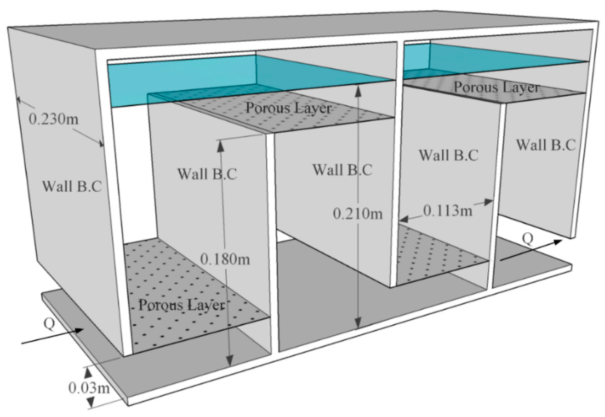
The objective of the present study is to numerically investigate the effect of porous baffles on the flow and transport characteristics in a widely used contact tank geometry that is reported in the literature. As shown in Figure 1, horizontal porous baffles are implemented at the entrance of each chamber in a conventional tank design. A second-order accurate numerical model is employed for the simulation of flow and tracer transport while using public domain CFD software OpenFOAM [23]. LES model is employed for the simulation of turbulence induced mixing of the conservative tracer with fluid. Horizontal porous baffles with three different porosities are used to investigate the effect of porosity on the mixing performance. Darcy-Forchheimer relation is employed for the characterization of flow through the porous media. Based on the tracer studies that were conducted for a conservative tracer, hydraulic and mixing efficiencies are evaluated while using different indicators for each porosity. Performance of the porous zone that yields the best efficiency is compared with the performance of the recently developed slot-baffle design. Energy loses are calculated based on a dimensionless energy efficiency index for the evaluation of the efficiency of the flow through system and results are discussed in detail.
2. Numerical Model
2.1. Governing Equations
Flow and transport of the conservative tracer are simulated while using the LES model to predict the turbulence induced mixing of the tracer with the fluid inside the computational domain. The filtered equations for the incompressible fluid are mass, momentum, and transport equations in the following conservative form:
here, overbar indicates the grid-filtered value of a variable in the LES, t is the time, ρ is the density, is the velocity component in the i-direction (x, y and z directions), p is the pressure, is the kinematic viscosity, is the source term for the porosity effects, is the concentration of conservative chemical, and is the turbulent diffusivity, which is calculated by dividing eddy viscosity by the turbulent Schmidt number . The Schmidt number is defined as the ratio of the momentum diffusivity to mass diffusivity in turbulent flows. A universal value for the turbulent Schmidt number is not available in the literature. In this study, the Schmidt number is selected as 1000 in order to be consistent with the literature [9].
Unresolved turbulent eddies are approximated using a sub-grid scale (SGS) model that was developed by Smagorinsky [24]. The SGS stresses in Equation (2) are computed from the following Boussinesq approximation:
where is the filtered strain-rate tensor and is called as SGS eddy viscosity:
where is the filter size and is the Smagorinsky constant, which is set to 0.1 in the present study.
A source term is incorporated into the momentum equations to represent porous effects. Darcy-Forchheimer relation is used to characterize the flow through the porous media. This two-part relation indicates viscous and inertial resistance to the flow [25]:
here, D and F coefficients are known as Darcy-Forchheimer coefficients, which are calculated based on the porosity and median diameter from the following equations [25,26]:
2.2. Boundary Conditions
Physics of the present problem is characterized by using the boundary conditions at inlet, outlet, walls, and free-surface (Figure 1). Open source CFD code OpenFOAM offers several alternative boundary conditions, depending on the problem analyzed. At the inlet and outlet of the computational domain, mapped boundary conditions are applied for the flow variables velocity, pressure, turbulence kinetic energy and turbulence viscosity. Mapped boundary condition in the OpenFOAM library allows for applying the average flow velocity at the inlet and to set the same Reynolds number as in the literature for the comparison of the numerical results with the existing results. Symmetry boundary condition is used on the free-surface, since oscillations on the free-surface are assumed to be negligible in the present problem.
A structured mesh system is adopted clustering smaller elements near the solid walls and free-surface to capture high gradients in flow variables in those regions. A detailed mesh independent study was carried out for the same tank geometry in the previous studies [1,13]. The resultant mesh consists of 1,687,500 cells in the computational domain. The cell resolution adjacent to the solid walls is fine enough to capture boundary layer effects arising from the adverse pressure gradients. Boundary conditions applied on the walls are no-slip condition for the velocity, zeroGradient for the pressure, kqRWallFunction for the turbulence kinetic energy, nutkWallFunction for the turbulence viscosity, and nutUSpaldingWallFunction for the nuSGS in OpenFOAM.
Unsteady simulation of the flow in the tank is performed using the standard solver pimpleFOAM in OpenFOAM. Allowable time step size is computed from the Courant stability condition during the simulation. The Courant number is set to 0.5 in the present study to capture unsteady variations of eddies near the corners of the baffles accurately. Tracer studies are usually performed while using frozen flow approach [4,5,6,11,15,16,27], in which the advection-diffusion equation is solved solely for a constant flow field obtained from the steady-state solution. Although this approach can simulate the tracer transport in a relatively short duration, turbulent fluctuation induced mixing of the tracer cannot be simulated by this approach. The relevant standard solver is modified to include the numerical solution of the transport equation (Equation (3)) with the governing flow equations in the same time-loop. The usage of an open source CFD code in the numerical simulations allowed for modifying the standard solver for the present problem. Turbulent diffusivity in Equation (3) is computed from the interior turbulence field at each time step of the simulation. Convective and diffusive terms in the governing equations are discretized using second-order accurate linearUpwind and linear methods to reduce truncation errors arising from the discretization of the partial differential equations. Unsteady terms are discretized using the second order implicit backward method. The overall numerical method ensures the second order accuracy in both spatial and time domains. Numerical simulations are performed in parallel while using domain decomposition method at High Performance and Grid Computing Center (TRUBA).
Porous baffles with 3 mm thickness were located at the entrance of each chamber, as shown in Figure 1. Naturally occurring fresh-water sediments with experimental results have been used in the literature to determine the properties of the material in the porous layer [28,29]. Sieve analysis was performed to determine the median diameter of the natural material and column experiments were carried out while using a constant head influent reservoir and fixed wall permeameter for porosity. It is modelled by considering 3 mm thickness of these natural materials are fixed horizontally in the tank by fixing a metal sieve with the same porosity. The porous layer is characterized by the median diameter d50 and the corresponding porosities and the calculated Darcy-Forchheimer coefficients are shown in Table 1.
3. Results and Discussions
Flow and transport of the tracer are simulated using five different contact tank designs, namely conventional, slot-baffle, and porous layers with three different porosities. Flow features are analyzed for each tank design by means of time-averaged flow field obtained from the LES studies. Tracer studies are carried out to obtain RTD and cumulative RTD plots. Efficiency indexes are computed for the assessment of the hydraulic and mixing efficiencies of each tank design. Dimensionless energy efficiency index is used for the evaluation of the energy losses in the flow [3].
3.1. Flow Analysis
Previous studies showed that the predicted jet velocity is high in the initial stage of the LES, then tend to decrease, and stabilize as the simulation continues [1]. Thus, time-averaged flow quantities are calculated starting from 50 s of the simulation to exclude the possible effects arising from the initial conditions and the simulation is performed for 400 s in order to obtain adequate data for time averaging.
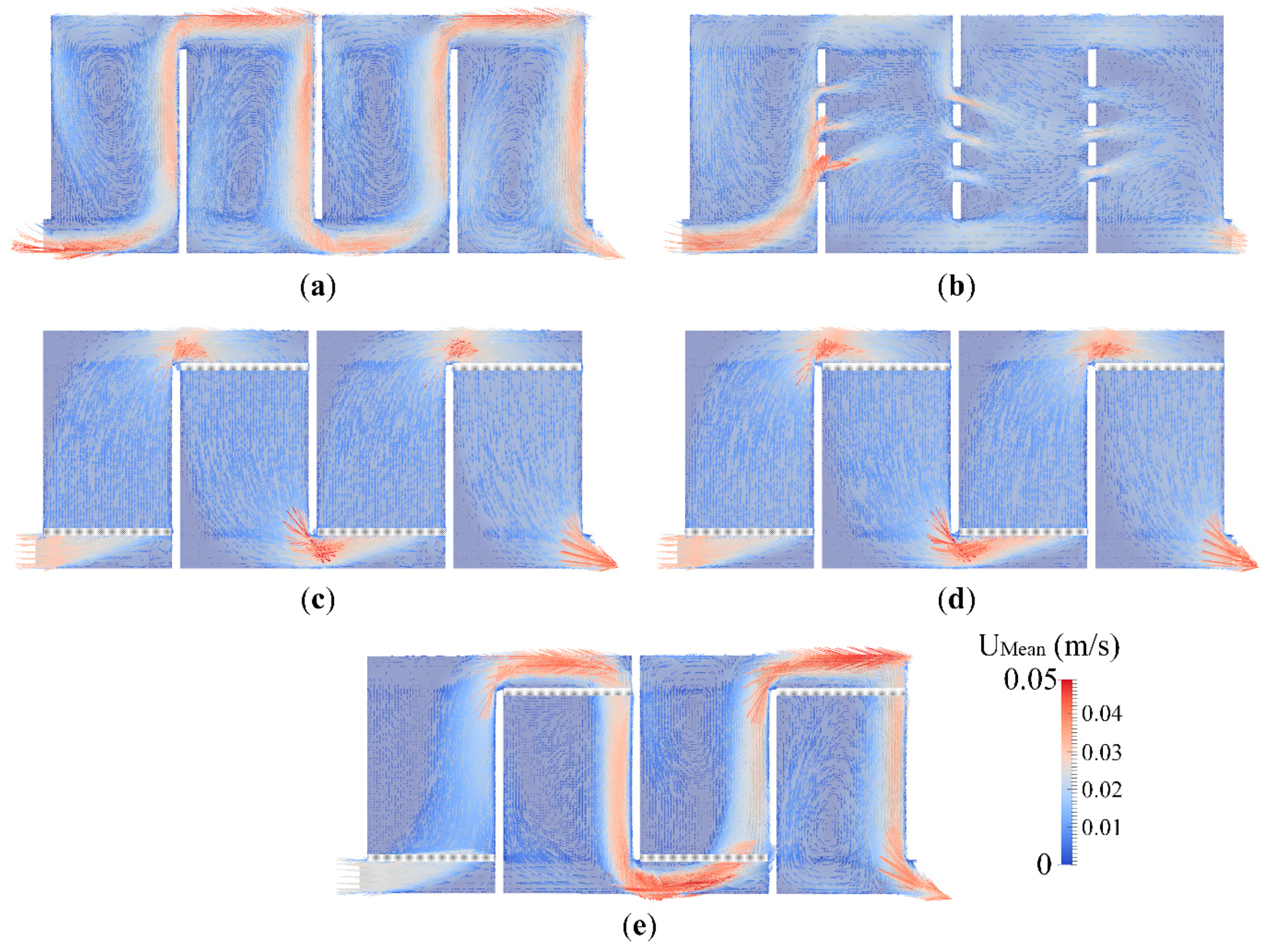
Time-averaged velocity vectors at the vertical plane passing at the center of the tank are shown in Figure 2 for each tank design. The flow field in Figure 2a shows a drastic short-circuiting due to large recirculation zones that cover most of the chamber. The injected disinfectant at the inlet will be advected by high velocity parcels in the jet region, which is believed to be the main source of the short-circuiting in a contact tank. Moreover, small recirculation zones are observed at the entrance of the chambers due to energetic eddies near the corners, which could be predicted by the LES. The core of the recirculation zone was found to be near the center of the chamber in the RANS simulations that were conducted in the literature [1,16]. However, small recirculation zones predicted by the LES near the baffle corners forced the core of the recirculation zone to shift up or down depending on the flow direction in each chamber. As shown in Figure 2b, the slot-baffle design that was proposed by Aral and Demirel [12] causes the jets emerging from the slots to impinge to the dead zone in the neighboring chamber and this reduces the momentum of the main jet, which is an indicator for suppressing the short-circuiting. Specifically, the slot-baffle design not only mitigate the short-circuiting, but also increase mixing by creating new mixing zones from the momentum of the main jet that moves parallel to the baffles. Moreover, the slot-baffle design reduces the energy loses in the flow through the contact system by both reducing the fluid-solid zones and increasing the fluid-fluid zones, which will be discussed below.
Effect of the porous baffle on the mean flow field is seen in Figure 2c–e for different porosities. As the porosity decreases, streamlines tend to be straight and recirculating flow inside the chamber turns to the plug-flow. This observation suggests that the chambers are devoid of any high velocity parcels and almost quiescent regions form near the corners for the porous designs of 1 and 2. Although the flow features are seemed to be identical in porous designs 1 and 2, jet and recirculation regions are observed when the Porous design 3 is used, similar to the conventional design. Time-averaged flow field for the Porous design 3 shows that the flow features in the chambers are no longer periodic due to the locations of the porous layers. If we consider folding the four-chambered tank geometry in half, the porous zones will not collapse onto each other. This suggests that implementing porous layers at the entrance of each chamber causes the flow structure to be no longer periodic, even if the tank geometry remains periodic. The periodicity would be guaranteed by shifting the locations of the porous layers. However, such a design would not be proper for the enhancement of the efficiency of the contact tank due to fact that the porous layer should be implemented at entrance of the chamber to increase the efficiency.
Comparison of the time-averaged flow fields in chambers two and three are shown in Figure 3 for the Porous design 2 and the slot-baffle design. While the porous zone converts the recirculating streamlines to straight streamlines and produces plug-flow inside the tank, the slot-baffle design utilizes the momentum of the main jet to create new mixing zones in the neighboring chamber. These two different ideas have contrary effects on the hydraulic efficiency of the contact system. If we consider that the available regulations strongly recommend creating plug-flow inside the tank, according to the suggested index values, the porous design seems to have a positive effect on the performance of the contact system. However, the slot-baffle design provides the required contact time by increasing the mixing zones.
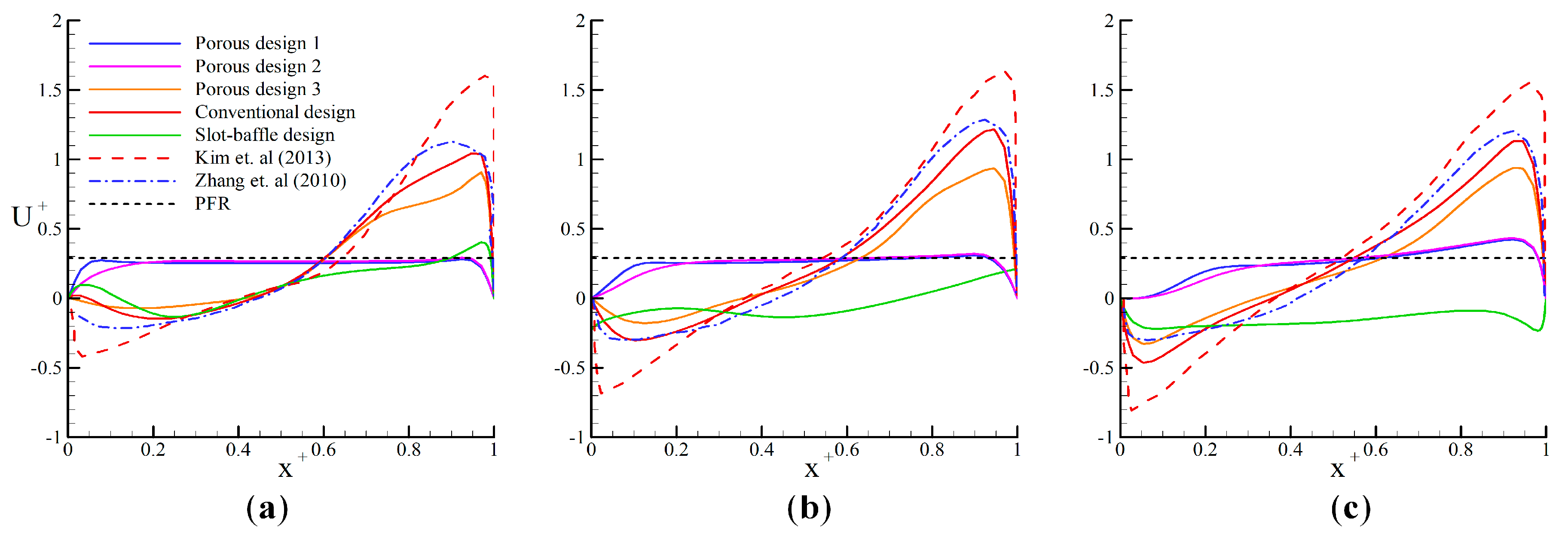
Distributions of the vertical velocity component over the chamber width are compared in Figure 4 for each tank design, along with the previous results reported for the conventional design. The spatial coordinate and the velocity are non-dimensionalized using the chamber width and the inlet velocity, respectively. The present results for the conventional design are consistent with the results that were reported by Zhang et al. [16]. However, Kim et al. [8] over predicted the magnitude of the jet velocity. Results of the Porous design 3 is identical to the conventional design, which shows the prominent effect of the porosity on the resultant flow field. However, porous designs 1 and 2 could successfully suppress the short-circuiting and turn the recirculating flow to the plug-flow, since the velocity distributions approach to that of PFR (plug-flow reactor). The velocity profiles of the slot-baffle design are completely different from the velocity profiles of other designs since the slot-baffle design significantly alters the flow field by creating new mixing zones.
3.2. The Energy Efficiency
Prediction of the energy loses in a contact tank is important for the assessment of the energy requirements to drive the flow by a pump in a tank. A novel contact system may cause the friction induced energy loses to increase significantly, even though hydraulic and mixing efficiencies increase. Overall, the economic contribution of the novel design should be evaluated by considering improvements not only in hydraulic and mixing efficiencies, but also in energy efficiency. The following dimensionless energy efficiency index that is proposed in [3] can be used for the evaluation of the energy efficiency of a contact tank:
where is the specific weight of the fluid, is the tank volume, is the water depth in the tank, and is the energy consumption rate that can be calculated from the following relation [30],
here (Pa) is the pressure drop between the inlet and outlet of the tank, (m3/s) is the flow rate, and is the mechanical efficiency constant of the pump, which is set to 0.5 [2]. The pressure drop is computed from the CFD results.
Energy efficiency indexes are calculated and shown for each tank design in Table 2. Implementation of the porous layer into the contact tank increases the energy losses due to the additional drag and viscous forces in the porous zone. As the porosity decreases, the energy efficiency of the system decreases. The Porous design 1 reduces the energy efficiency by approximately 33%. In contrast, the slot-baffle design has increased the energy efficiency by 67% as compared to the conventional design.
3.3. Tracer Studies
Tracer studies are performed employing the modified solver to determine hydraulic and mixing indexes relying on the RTD plots. Pulse injection is carried out injecting the constant tracer concentration at the inlet during s. Tracer simulations are performed during four theoretical mean residence time to observe that the total injected concentration leaves the domain. Most of the injected concentration volume is entrapped in the dead zones and it requires certain time to leave the contact tank. In order to be consistent with the literature and to observe the total injected concentration at the outlet, the tracer concentration is non-dimensionalized as . The cumulative concentration that is observed at the outlet section is calculated from , where is the dimensionless time. It should be noted that the tracer is conservative, in which chemical reactions are not taken into account.
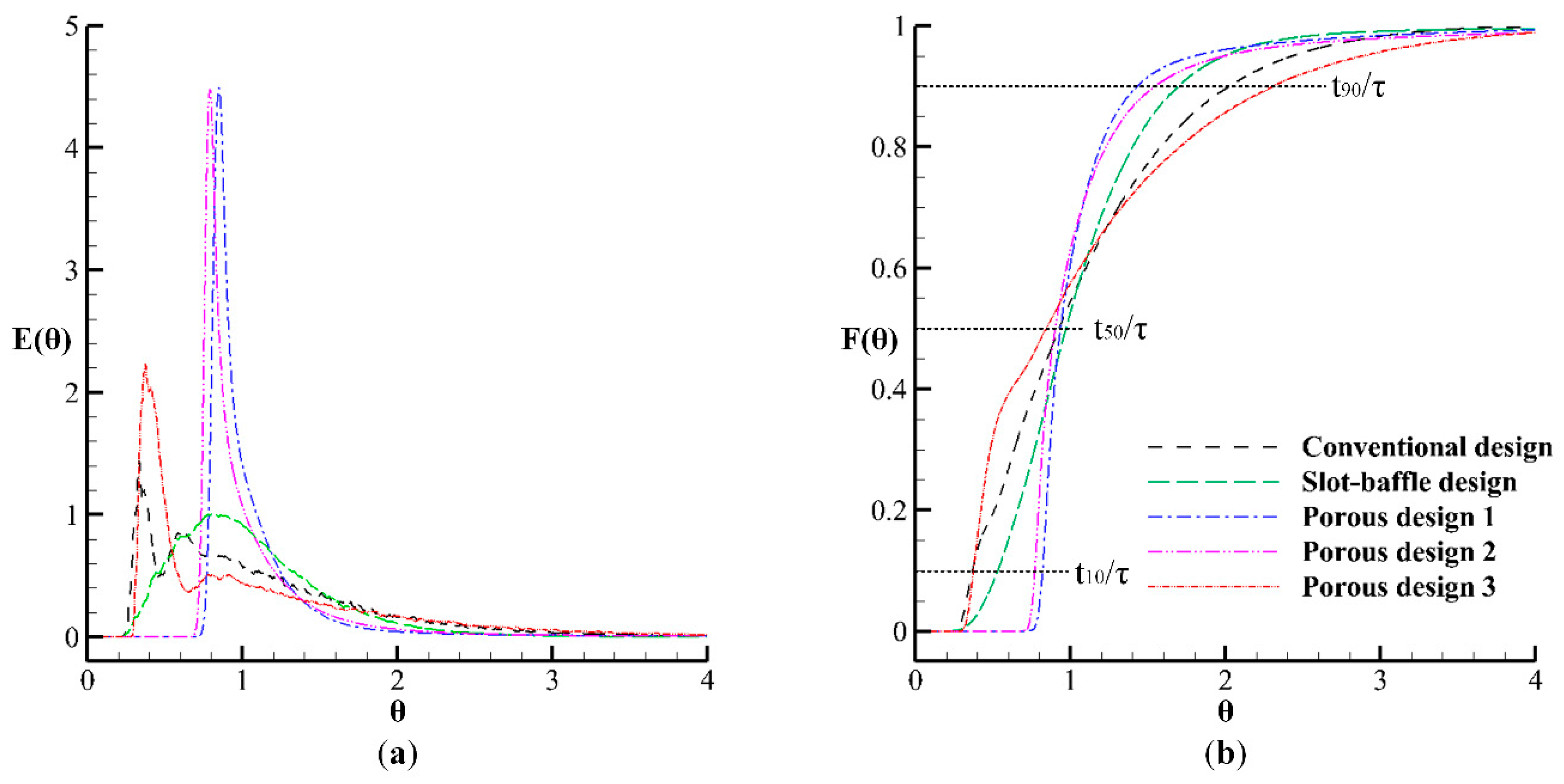
The RTD and cumulative RTD plots are shown in Figure 5 for each tank design. The peak of the dimensionless concentration shifts to the right and approaches unity for porous designs 1 and 2, which is another evidence of porous design turning the recirculating flow to the plug-flow successfully. On the other hand, the Porous design 3 could not increase the hydraulic efficiency due to its high porosity. This observation reveals that the porosity significantly affects the hydraulic efficiency of the contact tank and a detailed analysis is required for the optimization of the porosity for specific flow conditions in a contact system. Porous designs 1 and 2 represent relatively higher peaks when compared to the conventional design, since the injected tracer is transported by the bulk flow, which is attributed to the plug-flow that is formed by porous zones having low porosities. This feature of the tracer transport through porous media will be represented in the subsequent figure. Although the porous zone causes the peak of the RTD to increase, the slot-baffle significantly decreases the peak as compared to the conventional design in the RTD, which is the main difference between these two ideas. While porous zones form a bulk flow in which dispersion effects do not seem to be effective, the injected tracer concentration in the slot-baffle appears to leave the tank in a relatively long time duration from the time at which the tracer is first observed at the outlet. Moreover, the slot-baffle design turns the dead zones into active mixing zones, owing to the impingement of the subsequently created jets to the recirculation zones. More specifically, one can be said that the slot-baffle design increases the efficiency of the contact tank by increasing the dispersion effects, whereas the porous design increases the hydraulic efficiency by transforming the recirculating flow to the plug-flow, in which the dispersion effects are almost absent. If we consider that the Reynolds number in the conventional design is Re = 2740, which is in the transition region from laminar to turbulence, the Reynolds number of the flow decreases due to the viscous and inertial resistance in the porous zone, such that laminar flow occurs. The following important question arises at this point: “Can we simulate the laminar flow using the LES?” This question will be discussed in detail in the subsequent section.
Efficiency of the contact system is assessed while relying on the available indexes, which are obtained from the cumulative RTD plot in Figure 5b. The relevant parameters are determined from Figure 5b and calculated indexes are shown for each tank design in Table 3. Previous studies show that the θ10, which is so-called as “baffling factor”, can be used for the assessment of the hydraulic efficiency of the contact tank [31]. The Porous design 1 increased the hydraulic efficiency of the conventional design by 134%, which is a prominent improvement for the present problem. The slot-baffle design has increased the hydraulic efficiency by 52%. As the porosity decreases, the baffling factor approaches unity and the flow inside the contact tank approaches plug-flow. Apart from the porous designs, the slot-baffle design increases the baffling factor with increasing mixing inside the chambers. The U.S. EPA regulations [32] recommend that the Mo index is less than 2 for an effective design even if the Mo index theoretically takes values in the range of 1 to 30. Note that the Mo index approaches unity for ideal plug flow, the EPA regulations recommend forming plug-flow inside the tank for an ideal contact system. According to the Mo index, the Porous design 1 increased the efficiency of the conventional tank design by 68% and the slot-baffle design increased the efficiency by 42%. The efficiency of the contact system has been increased from “poor” to “good” by porous designs 1 and 2, and from “poor” to “fair” by the slot-baffle design according the suggested Mo index ranges by [33]. However, the Porous design 3 reduced the efficiency of the conventional tank design. This suggests that the porosity of the horizontal porous layer should be investigated in order to determine the optimum porosity.
The following AD index can be used for the assessment of the performance of the contact system [7,9]:
Efficiency of the contact tank has increased from “compromising” to “good” by the Porous designs 1, 2, and 3, according to the suggested ranges for the AD in [9]. However, their energy efficiency is rather low, as shown in Table 2. The AD index also shows a decreasing trend in the porous baffle designs as the porosity of the baffles increase. For the porous design, the increase in efficiency is mainly due to hydraulic performance in view of values of the porous baffle design. According to the AD index, the slot-baffle design slightly reduced the efficiency of the contact tank relative to conventional design due to the increase in the turbulence created, which increases mixing significantly, as seen in RTD plots, but also decreases the hydraulic efficiency of the contact tank. According to the AD index, the slot-baffle design remains in a compromising range. However, the increase in turbulence increases the energy efficiency of the slot-baffle contact tank significantly, relative to other designs, as seen in Table 2, which is an important gain.
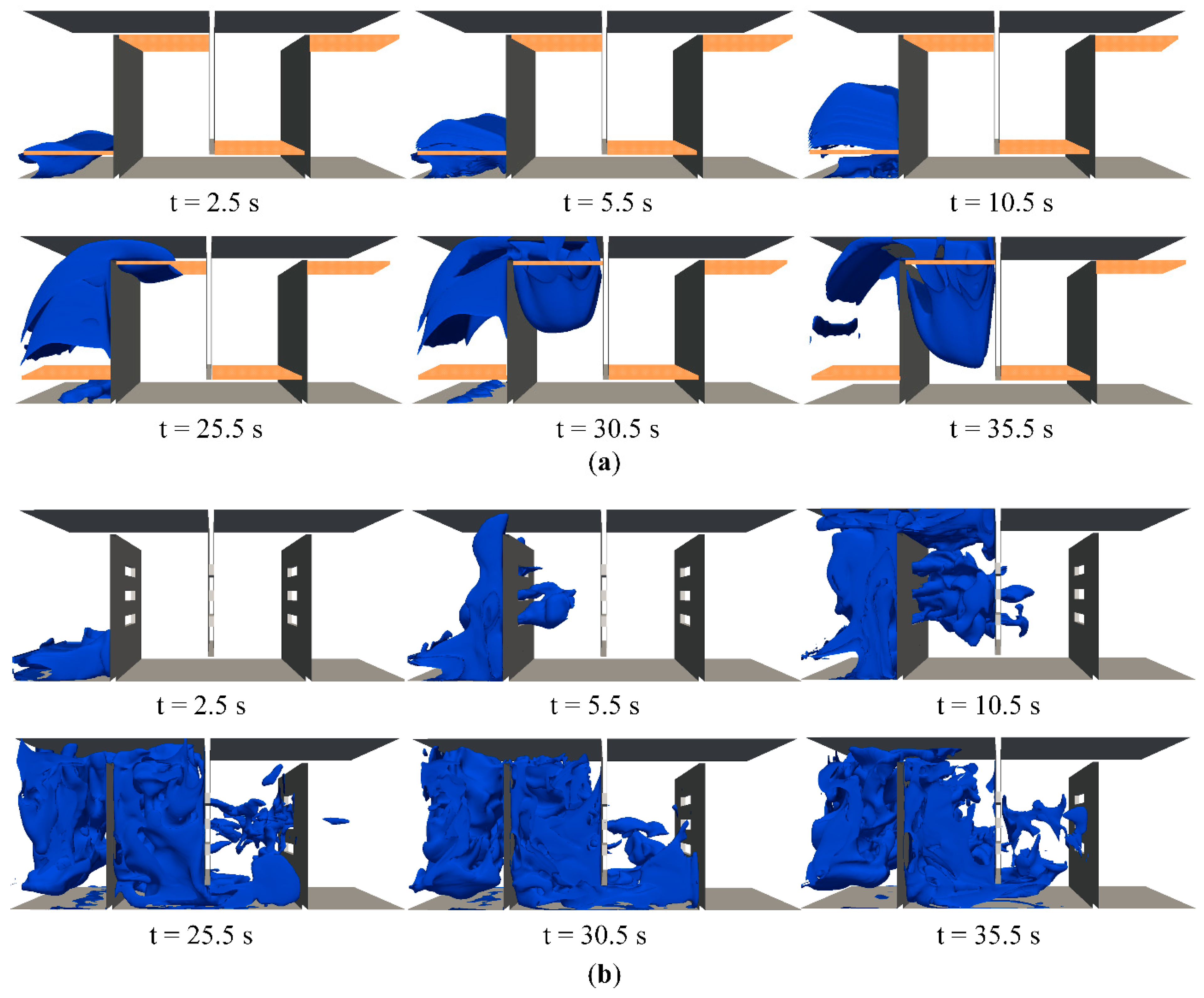
Based on the tracer simulation results, the transport of the tracer is shown at different instants of time for the Porous design 2 and the slot-baffle design in order to compare the performance of each design by means of tracer transport (Figure 6). The injected tracer is advected by the bulk flow and dispersion effects are almost absent. Some part of the tracer concentration is blocked by the porous layer and it remains below the first porous zone. Dispersion effects are dominant in the slot-baffle design since the background of this idea is to create new mixing zones utilizing the momentum of the main jet, which can be stated as “to kill two birds with one stone”.
3.4. LES Solution of the Laminar Flow
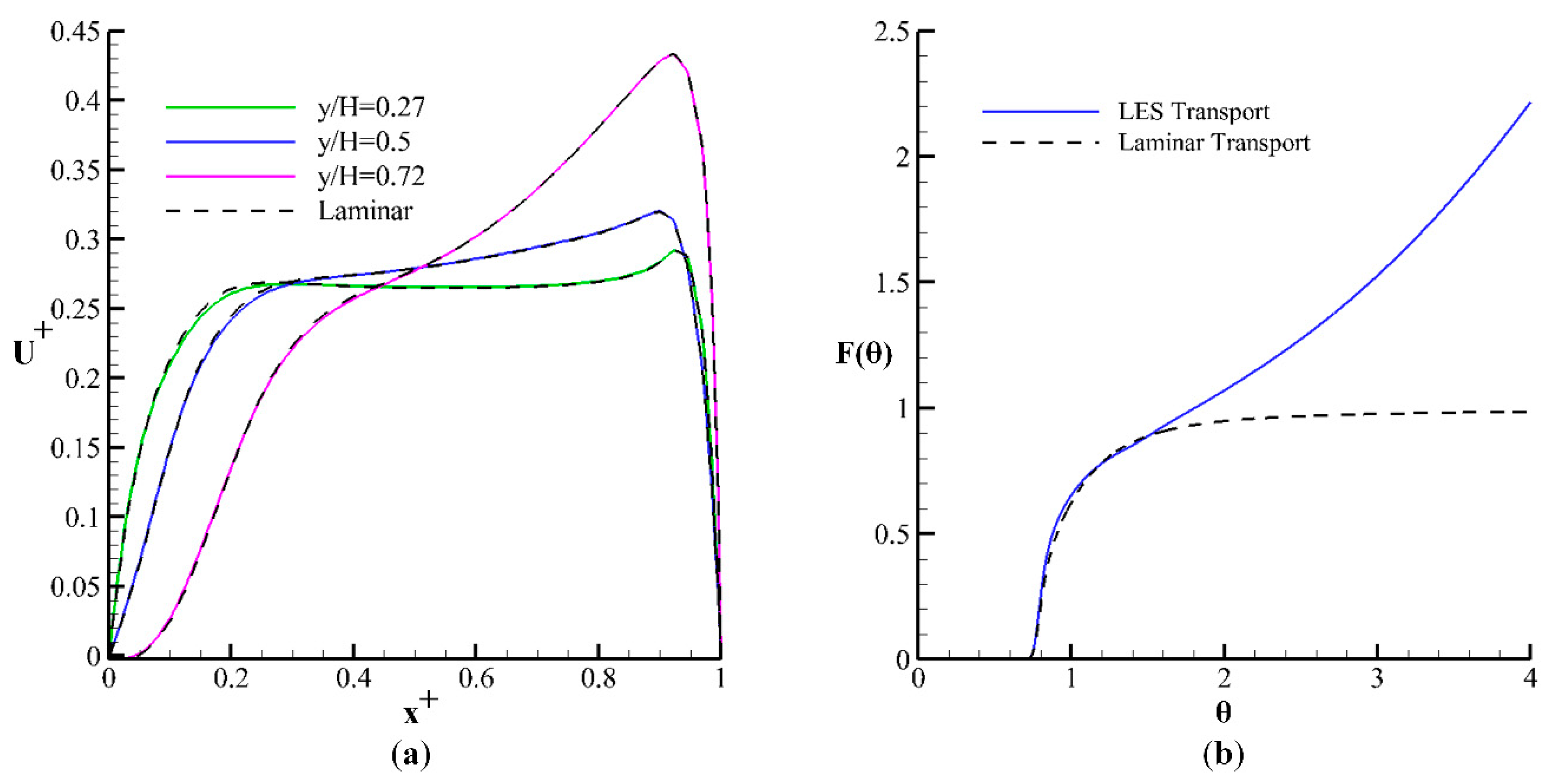
As the Reynolds number decreases due to the drag and viscous resistance in the porous zone, the flow turns to laminar flow in the contact tank system. The applicability of the LES for the simulation of laminar flow should be tested for the present problem. Previous studies showed that the LES could successfully simulate the laminar flow over backward-facing step using the LES, whereas the RANS approach produced inconsistent results [34]. In order to show the reliability of the present LES model for the laminar flows, the flow over Porous design 2 is simulated while using a laminar flow solver icoFOAM and distributions of time-averaged flow velocities are compared with the results of the LES at different elevations in Figure 7a. Dashed and solid lines show the laminar and LES results, respectively. A good agreement between the LES and laminar results proves that the present LES model could accurately simulate the laminar flow. The behavior in the transport simulation in Figure 7b is interesting. When the transport of the tracer is performed, including turbulence viscosity and Schimidt number in Equation (3), the cumulative tracer concentration starts to increase after a certain of time due to an artificial source arising from the numerical solution of the advection-diffusion equation. The continuous line in Figure 7b shows the solution of the flow and transport by the LES and the dashed line represents the flow by LES but transport by laminar. In the latter case, only the molecular diffusivity is considered excluding the turbulence viscosity in the LES. In order to exclude the possible effects arising from the local laminar flow conditions, Direct Numerical Simulation (DNS) should be used for both flow and tracer transport, which requires a long time duration to achieve time-averaged flow field.
4. Conclusions
In this study, the flow and transport of a conservative tracer are carried out in contact tanks having horizontal porous layers with different porosities. LES is used for the simulation of instantaneous mixing of the tracer. Darcy-Forchheimer relation characterizes the flow through the porous layer. Simulated flow and transport results for the porous layers are compared with the conventional and slot-baffle designs. Efficiency of the contact tanks are evaluated based on the available hydraulic and mixing indicators in the literature. The following conclusions are drawn from the numerical simulation results.
Implementation of the porous layers at the entrance of each chamber successfully mitigate recirculation effects and turn the recirculating and jet flows to the plug-flow. Porous designs 1 and 2 increased the hydraulic efficiency from “poor” to “good”, according the baffling factor. As the porosity decreases, the baffling factor of the contact tank obtained from the tracer studies approaches unity and the flow velocities decrease, as well as the flow inside the chambers becomes laminar due to the viscous and inertial resistance in the porous zone. Dispersion and mixing effects decrease in the porous designs even though porous layers increase the hydraulic efficiency by suppressing the recirculation effects. Decreasing the porosity of the layers causes friction induced energy loses to increase due to a severe increase in viscous and inertial resistance in the porous layer. On the contrary, in the slot-baffle design, subsequently created jets from the momentum of the main jet impinge to the dead zone and form active mixing zones in the neighboring chamber. While the porous designs increase the efficiency of the contact tank by turning the flow to the plug-flow and reducing the dispersion effects, the slot-baffle design enhances the overall efficiency of the contact system by increasing the mixing effects. The Mo index is less than 2 in the Porous design 1, which is recommended by the U.S. EPA regulations [32] for an ideal contact system. The energy efficiency of the contact system is also evaluated using the energy efficiency index. The Porous design 1, which has the minimum porosity and yields the maximum hydraulic efficiency, reduced the energy efficiency of the contact by 33% when compared to the conventional tank design due to the additional energy losses in the porous zone. The slot-baffle design has increased the energy efficiency of the conventional design by 67% since subsequently created jets emerging from the slots reduced the fluid-solid layers in the contact system.
Author Contributions
Conceptualization, E.D. and M.M.A.; Methodology, M.A.K. and E.D.; Software, M.A.K. and E.D.; Validation, M.A.K. and E.D.; Formal Analysis, M.A.K., E.D. and M.M.A.; Investigation, M.A.K., E.D. and M.M.A.; Resources, M.A.K; Data Curation, M.A.K.; Writing-Original Draft Preparation, M.A.K.; Writing-Review & Editing, E.D. and M.M.A.; Visualization, M.A.K.; Supervision, M.M.A.; Project Administration, E.D.; Funding Acquisition, E.D.
Funding
This research was funded by Scientific and Technological Research Council of Turkey (TUBITAK) grant number [217M472].
Acknowledgments
The numerical calculations reported in this paper were fully performed at TUBITAK ULAKBIM, High Performance and Grid Computing Center (TRUBA resources).
Conflicts of Interest
The authors declare no conflict of interest.
References
- Demirel, E.; Aral, M.M. Unified analysis of multi-chamber contact tanks and mixing efficiency evaluation based on vorticity field. Part I: Hydrodynamic analysis. Water 2016, 8, 495. [Google Scholar] [CrossRef]
- Demirel, E.; Aral, M.M. Unified analysis of multi-chamber contact tanks and mixing efficiency evaluation based on vorticity field. Part II: Transport analysis. Water 2016, 8, 537. [Google Scholar] [CrossRef]
- Demirel, E.; Aral, M.M. An evaluation of performance of efficiency indexes for contact tanks. J. Environ. Eng. 2018, 144, 1–13. [Google Scholar] [CrossRef]
- Amini, R.; Taghipour, R.; Mirgolbabaei, H. Numerical assessment of hydrodynamic characteristics in chlorine contact tank. Int. J. Numer. Methods Fluids 2011, 67, 885–898. [Google Scholar] [CrossRef]
- Angeloudis, A.; Stoesser, T.; Falconer, A.R. Predicting the disinfection efficiency range in chlorine contact tanks through a CFD-based approach. J. Water Res. 2014, 60, 118–125. [Google Scholar] [CrossRef] [PubMed]
- Angeloudis, A.; Stoesser, T.; Gualtieri, C.; Falconer, R.A. Contact tank design impact on process performance. Environ. Model. Assess. 2016, 21, 563–576. [Google Scholar] [CrossRef]
- Gualtieri, C. Analysis of the effect of baffles number on a contact tank efficiency with Multiphysics 3.3. In Proceedings of the COMSOL User Conference, Napoli, Italy, 23–24 October 2007. [Google Scholar]
- Kim, D.; Elovitz, M.; Roberts, P.J.W.; Kim, J.H. Using 3D LIF to investigate and improve performance of a multi-chamber ozone contactor. J. Am. Water Works Assoc. 2010, 102, 61–70. [Google Scholar] [CrossRef]
- Kim, D.; Stoesser, T.; Kim, J.H. The effect of baffle spacing on hydrodynamics and solute transport in serpentine contact tanks. J. Hydraulic Res. 2013, 51, 558–568. [Google Scholar] [CrossRef]
- Teixeria, E.D.; Siqueira, R.N. Performance assessment of hydraulic efficiency indexes. J. Environ. Eng. 2008, 134, 851–859. [Google Scholar] [CrossRef]
- Wang, H.; Shao, X.; Falconer, R.A. Flow and transport simulation models for prediction of chlorine contacttank flow-through curves. Water Environ. Res. 2003, 75, 455–471. [Google Scholar] [CrossRef] [PubMed]
- Aral, M.M.; Demirel, E. Novel slot-baffle design to improve mixing efficiency and reduce cost of disinfection in drinking water treatment. J. Environ. Eng. 2017, 143, 1–5. [Google Scholar] [CrossRef]
- Demirel, E.; Aral, M.M. An efficient contact tank design for potable water treatment. Teknik Dergi 2018, 29, 8279–8294. [Google Scholar] [CrossRef]
- Zhang, J.; Martinez, A.E.T.; Zhang, Q. Indicators for technological, environmental and economic sustainability of ozone contactors. Water Res. 2014, 101, 606–616. [Google Scholar] [CrossRef] [PubMed]
- Wilson, J.M.; Venayagamoorthy, S.K. Evaluation of hydraulic efficiency of disinfection systems based on residence time distribution curves. Environ. Sci. Technol. 2010, 44, 9377–9382. [Google Scholar] [CrossRef] [PubMed]
- Zhang, J.; Martinez, A.E.T.; Zhang, Q. Reynolds-averaged Navier-Stokes simulation of the flow and tracer transport in a multichambered ozone contactor. J. Environ. Eng. 2013, 10, 450–454. [Google Scholar] [CrossRef]
- Yang, J.; Li, J.; Zhu, J.; Dong, Z.; Luo, F.; Wang, Y.; Liu, H.; Jiang, C.; Yuan, H. A novel design for an ozone contact reactor and its performance on hydrodynamics, disinfection, bromate formation and oxidation. Chem. Eng. J. 2017, 328, 207–214. [Google Scholar] [CrossRef]
- Higuera, P.; Lara, J.L.; Losada, J.I. Three-dimensional interaction of waves and porous coastal structures using OpenFOAM. Part I: Formulation and validation. Coast. Eng. 2013, 83, 243–258. [Google Scholar] [CrossRef]
- Brito, M.; Fernandes, J.; Leal, J.B. Porous media approach for RANS simulation of compound open-channel flows with submerged vegetated floodplains. Environ. Fluid. Mech. 2016, 16, 1247–1266. [Google Scholar] [CrossRef]
- Domingo, A.; Langmayr, D.; Somogyi, B.; Almbauer, R. A semi-implicit treatment of porous media in steady-state CFD. Transp. Porous. Med. 2016, 112, 451–466. [Google Scholar] [CrossRef] [PubMed]
- San, B.; Wang, Y.; Qiu, Y. Numerical simulation and optimization study of the wind flow through a porous fence. Environ. Fluid Mech. 2018, 1–19. [Google Scholar] [CrossRef]
- Pak, A.; Mohammadi, T.; Hosseinalipour, S.M.; Allahdini, V. CFD modeling of porous membranes. Desalination 2007, 222, 482–488. [Google Scholar] [CrossRef]
- OpenFOAM. The OpenFOAM Foundation; OpenCFD Ltd.: Bracknell, UK, 2015. [Google Scholar]
- Smagorinsky, J. General calculation experiments with the primitive equations, Part I: The basic experiment. Mon. Weather Rev. 1963, 91, 99–164. [Google Scholar] [CrossRef]
- Stefano, G.M.D. Modeling Thermal Energy Storage Systems with Open∇FOAM. Ph.D. Thesis, Politecnico di Milano, Milan, Italy, 2002. [Google Scholar]
- Ergun, S. Fluid flow through packed columns. Chem. Eng. Prog. 1952, 48, 89–94. [Google Scholar]
- Gualtieri, C.; Angeloudis, A.; Bombardelli, F.; Jha, S.; Stoesser, T. On the value for the turbulent Schmidt number in environmental flows. Fluids 2017, 2, 17. [Google Scholar] [CrossRef]
- Morgan, N.A. Physical properties of marine sediments as related to seismic velocities. Geophysics 1969, 34, 529–545. [Google Scholar] [CrossRef]
- Sperry, J.M.; Peirce, J.J. A model for estimating hydraulic conductivity of granular material based on grain shape, grain size, and porosity. Ground Water 1995, 33, 892–898. [Google Scholar] [CrossRef]
- Finnemore, J.E.; Franzini, J.B. Fluid Mechanics with Engineering Applications; McGraw Hill: New York, NY, USA, 2002. [Google Scholar]
- Lev, O.; Regli, S. Evaluation of ozone disinfection systems: Characteristics time T. J. Environ. Eng. 1992, 118, 268–285. [Google Scholar] [CrossRef]
- U. S. Environmental Protection Agency. Disinfection Profiling and Benchmarking Guidance Manual; Appendix, A. Rep. No. EPA 816-R-03-004; EPA: Washington, DC, USA, 2013. [Google Scholar]
- Gualtieri, C. Discussion of “Performance assessment of hydraulic efficiency indexes” by Edmilson Costa Teixeira and Rento do Nascimento Siqueira. J. Environ. Eng. 2010, 136, 851–859. [Google Scholar] [CrossRef]
- Gong, Y.; Tanner, F.X. Comparison of RANS and LES models in the laminar limit for a flow over a backward-facing step using OpenFOAM. In Proceedings of the Nineteenth International Multidimensional Engine Modeling Meeting at the SAE Congress, Detroit, MI, USA, 19 April 2009. [Google Scholar]
Figure 1.
Configuration of the porous baffle layers in the contact tank.

Figure 2.
Time-averaged velocity vectors on a vertical plane at the center of the tank: (a) Conventional; (b) Slot-baffle; (c) Porous design 1; (d) Porous design 2; and, (e) Porous design 3.
Figure 2.
Time-averaged velocity vectors on a vertical plane at the center of the tank: (a) Conventional; (b) Slot-baffle; (c) Porous design 1; (d) Porous design 2; and, (e) Porous design 3.

Figure 3.
Comparison of the time-averaged flow fields in chambers two and three for the (a) Porous design 2 and (b) Slot-baffle design.
Figure 3.
Comparison of the time-averaged flow fields in chambers two and three for the (a) Porous design 2 and (b) Slot-baffle design.

Figure 4.
Variation of the vertical velocity component over the chamber width at different elevations (a) y/H = 0.27; (b) y/H = 0.5; and, (c) y/H = 0.72 [8,16].

Figure 5.
(a) Residence Time Distribution (RTD) and (b) cumulative RTD plots.

Figure 6.
Transport of the tracer concentration at different time steps (a) Porous design 2 and (b) Slot-baffle design.
Figure 6.
Transport of the tracer concentration at different time steps (a) Porous design 2 and (b) Slot-baffle design.

Figure 7.
Comparison for the Large Eddy Simulation (LES) and laminar solutions of (a) flow and (b) transport results.
Figure 7.
Comparison for the Large Eddy Simulation (LES) and laminar solutions of (a) flow and (b) transport results.


Table 1.
Porosity of different zones.
| Screen Number | d50 (mm) | Porosity (ε) | D (cm−1) | F (cm−1) |
|---|---|---|---|---|
| 1 | 0.000774 | 0.31 | 2.76 × 10⁹ | 5.24 × 10⁴ |
| 2 | 0.001419 | 0.504 | 7.10 × 10⁷ | 4.78 × 10³ |
| 3 | 0.001899 | 0.802 | 6.26 × 10⁵ | 3.54 × 10² |
Table 2.
Energy efficiencies for different contact tank designs.
| Configuration | |||
|---|---|---|---|
| NW | 8.79 | 3.54 | 0.12 |
| Porous design 1 | 12.90 | 5.21 | 0.08 |
| Porous design 2 | 10.57 | 4.26 | 0.10 |
| Porous design 3 | 7.31 | 2.95 | 0.14 |
| Slot | 5.10 | 2.06 | 0.20 |
Table 3.
Characteristic time indexes for contact tank designs.
| Configuration | ||||
|---|---|---|---|---|
| Conventional | 0.369 | 2.030 | 5.493 | 1.632 |
| Porous design1 | 0.822 | 1.431 | 1.741 | 2.421 |
| Porous design 2 | 0.772 | 1.548 | 2.005 | 2.404 |
| Porous design 3 | 0.375 | 2.311 | 6.163 | 2.098 |
| Slot-baffle design | 0.532 | 1.698 | 3.192 | 1.491 |
© 2018 by the authors. Licensee MDPI, Basel, Switzerland. This article is an open access article distributed under the terms and conditions of the Creative Commons Attribution (CC BY) license (http://creativecommons.org/licenses/by/4.0/).
Share and Cite
MDPI and ACS Style
Kizilaslan, M.A.; Demirel, E.; Aral, M.M. Effect of Porous Baffles on the Energy Performance of Contact Tanks in Water Treatment. Water 2018, 10, 1084. https://doi.org/10.3390/w10081084
AMA Style
Kizilaslan MA, Demirel E, Aral MM. Effect of Porous Baffles on the Energy Performance of Contact Tanks in Water Treatment. Water. 2018; 10(8):1084. https://doi.org/10.3390/w10081084
Chicago/Turabian StyleKizilaslan, M. Anil, Ender Demirel, and Mustafa M. Aral. 2018. "Effect of Porous Baffles on the Energy Performance of Contact Tanks in Water Treatment" Water 10, no. 8: 1084. https://doi.org/10.3390/w10081084
Note that from the first issue of 2016, this journal uses article numbers instead of page numbers. See further details here.