Experimental Studies on the Stability Assessment of a Levee Using Reinforced Soil Based on a Biopolymer


Korea Institute of Civil Engineering and Building Technology (KICT), Goyang-Si 10223, Gyeonggi-Do, Korea
*
Author to whom correspondence should be addressed.
Water 2018, 10(8), 1059; https://doi.org/10.3390/w10081059
Submission received: 6 July 2018
/
Revised: 28 July 2018
/
Accepted: 8 August 2018
/
Published: 9 August 2018
(This article belongs to the Section Hydraulics and Hydrodynamics)
Abstract
:Cement and other similar compounds have been used to prevent a levee breach during a flood. However, the demand is increasing for eco-friendly and sustainable alternatives to replace the conventional method for levee stabilization and strengthening. To improve the durability and environmental friendliness of a levee, the Andong River Experiment Center applied a biopolymer, which is a new eco-friendly substance, to fabricate a levee model, and conducted a hydraulic model experiment to evaluate the reliability and stability of the new type of levee. An image analysis was applied to calculate the scale of the breaches of the levee slopes. Based on the experimental results obtained, the characteristics of the breach between an earthen levee and the proposed levee were compared. The stability of the levee body was also evaluated according to the thickness of the new substance. The ultimate aim of this study was to derive the optimal conditions by verifying the performance and effectiveness of the new substance in terms of levee breach factors such as overflow, seepage, or piping in a series of hydraulic experiments. In the future, the field application of these optimal conditions will be verified through a real-scale experiment.
1. Introduction
A river levee not only protects lower lands from flooding, but is also an environmentally important link between the land and rivers. Global climate change and urbanization have increased the incidences of abnormal floods exceeding the design flood discharge, and river levees have become more vulnerable to flood damage. Recently, old levees with deteriorating flood control functions have been breached for many different reasons, resulting in huge losses of both life and property. Typically, the levee breach during a flood is attributable to three main causes: overflow, erosion, and unstable body conditions. An overflow occurs when a flood runoff exceeds the conveyance of a river channel, or when the conveyance is reduced by sand, soil, or debris. Erosion occurs when a levee slope or bottom is scoured by an excessive flow velocity and shear stress in a steep river slope or bend. Instability of a levee body includes the piping of the body, and is caused by poor filling materials or levee body leakage. Finally, a levee breach also occurs in the collapse of a river-crossing structure or the interface of a structure using different materials from the levee. According to a previous report, overflows account for 40% of all levee breaches in South Korea.
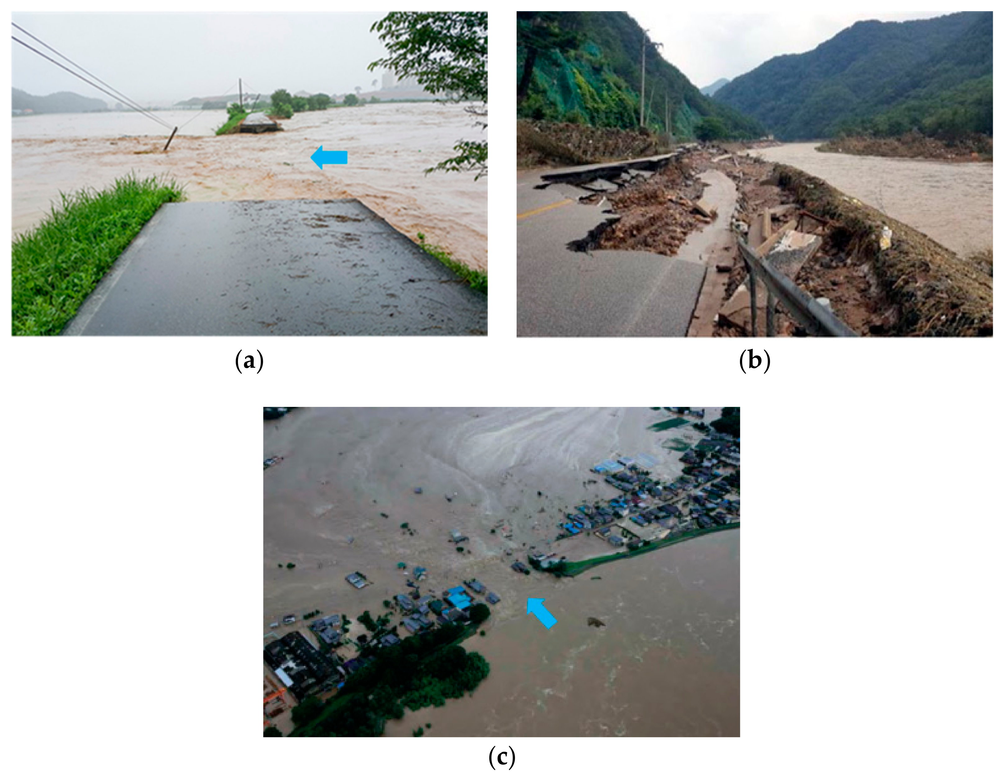
Among the recent cases of levee breaches in South Korea and other countries, the localized heavy rain in 2017 in Chungcheong of South Korea caused huge losses in property by scouring an interface between a river structure and levee, or by breaching the levee and revetment. In Ibaraki in Japan, the record-high rainfall in September 2015 broke the east levee of Kinu River, which was around 200 m in length, and caused enormous flood damage (Figure 1). Unfortunately, such cases of levee breach are continuously increasing.
Many advanced countries including Japan and the USA have legislated design criteria for levees, and are developing technologies to realize high-strength levees that are safe against flooding. In particular, the Netherlands has strengthened the design frequency of the flood response for levees, and implemented a national technology development program, led by Deltares, a large technical institute for integrated water resources and social infrastructure management, to improve the performance of its existing levees and protect them from erosion, flooding, and piping. In contrast, in South Korea, despite large amounts of money spent on flood control projects for levees and revetments, technologies for constructing strong levees or responding to levee breaches have not been fully developed. Accordingly, the same pattern of flood damage and restoration is repeated each year. Because an overflow occurs when a design flood has been exceeded, a complete breach of a levee from an overflow needs be prevented, particularly in areas where important facilities are located. In this regard, appropriate countermeasures should be established to protect life and property. To diminish and predict flood damage from a levee breach, hydraulic experiments should be conducted under various conditions. The stability of a levee also needs to be evaluated according to reinforcement methods and materials in order to minimize damage after a levee breach.
Existing studies on levees, which have been performed in South Korea and other countries, include small-scale experiments for understanding the formation and process of an overtopping breach or erosion according to the levee material (e.g., [1,2,3,4]); a levee model experiment under most real-scale conditions, which could minimize the scale effect for analyzing the breach behavior according to the seepage and overflow (e.g., [5,6,7,8,9]); an analysis of the retardation effects on a levee breach from the use of reinforcement methods (e.g., [10,11]); an investigation of improving the stability of the levee against erosion and infiltration using mixed materials with cement (e.g., [12,13,14,15]); and methods of improving soil behavior using biopolymers (e.g., [16,17]). All advanced countries should establish and implement effective countermeasures to prevent levee erosion from flooding. This study conducted experiment-based research using a biopolymer, which is an eco-friendly material for geotechnical engineering, as a part of a technical development project for responding to levee erosion and seepage and improving unstable levees. A new biopolymer was developed by a research team at the Korea Advanced Institute of Science and Technology (KAIST), which participated in our project.
This study is innovative in that this new substance was applied in the construction of a levee. It is expected that the biopolymer will improve the durability and environmental friendliness of the levee along with the soil. A hydraulic experiment was performed at the Andong River Experiment Center. A method for evaluating the stability of levees using the developed biopolymer has been established. In the future, further experiments will be conducted to determine the optimal formulas of the new technology for each factor, such as the overflow, seepage, and piping, and the formulas will be applied to real-scale experiments.
2. Hydraulic Model Experiment
2.1. Experimental Setup
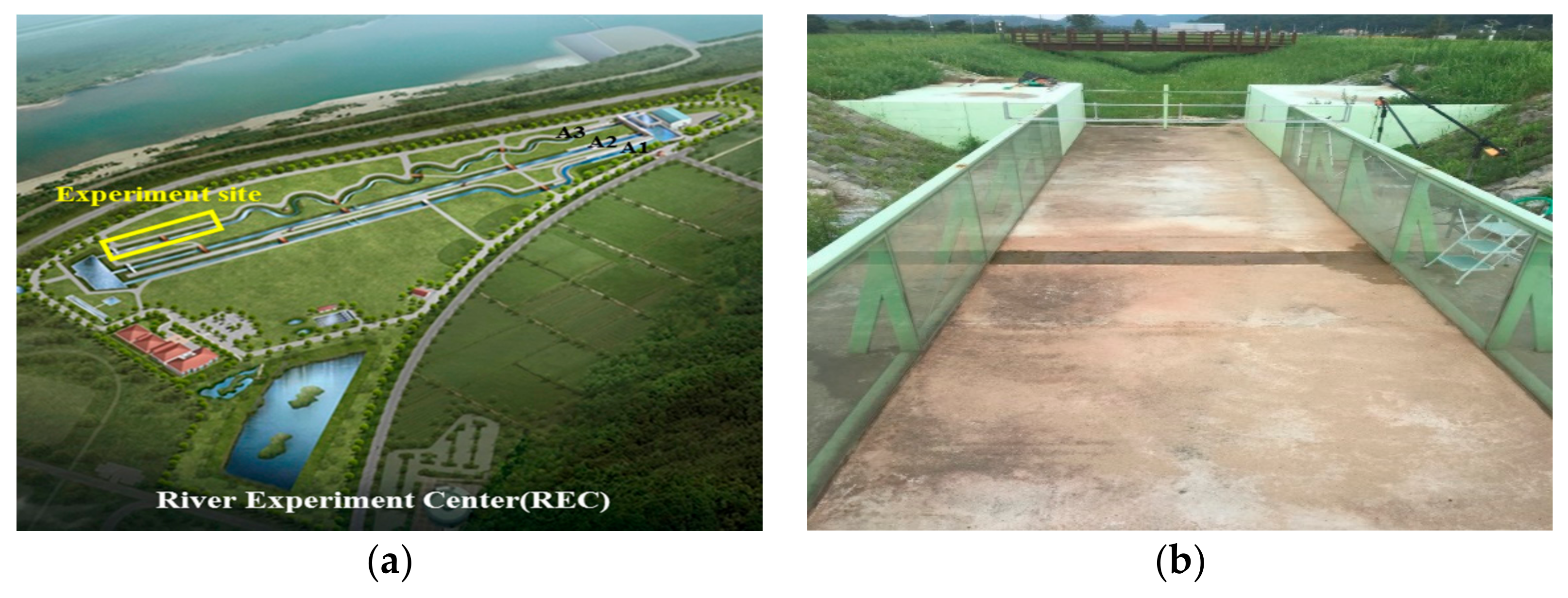
A mid-sized levee of 1 m in height, 1 m in length, and 3 m in breath, with a 1:2 slope and 5 m length, was constructed at the Andong River Experiment Center (REC) of the Korea Institute of Civil Engineering and Building Technology (Figure 2). The aim of the hydraulic experiment was to comparatively analyze the behaviors of levees during an overtopping breach between an earthen levee and the proposed levee using the newly developed substance, and to verify the retardation effects on the levee breach according to the thickness applied.
To closely analyze the breach of a levee slope from an overflow, an image measuring system was installed in the experimental channel, and five GoPro cameras and one video camera were placed in front and on both sides of the breaching part of the levee. The entire experiment was filmed at different angles in real-time to analyze the surface scouring of the slope and the breached sections. The breach of a levee crest was filmed using a drone.
2.2. Experiment Method
Because several preliminary experiments have already clarified that an earthen levee frequently undergoes an initial breach formation in the interface between the levee crest and slope during an overflow, this zone was identified as a vulnerable area to an overtopping breach, and was determined to be covered by the newly developed substance.
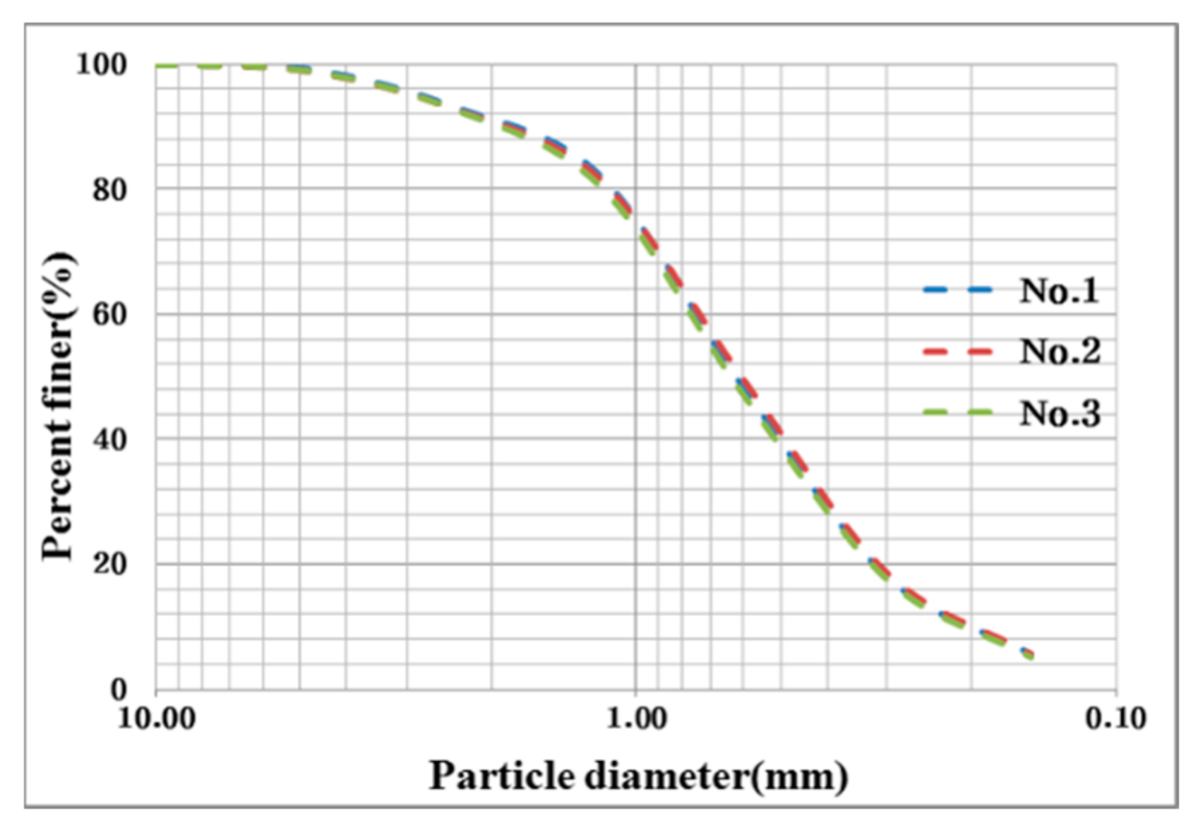
The sand used in the experiment, based on the soil classification system, is a uniform well-graded sand (SW), in which 50% is retained on or above a No. 200 sieve (Figure 3). By using this type of soil, which is vulnerable to crack, the performance of the bio-polymer mixed with the most vulnerable of materials becomes more apparent, and the formation of overflow breach cross-sections is induced. Since the sand used in the experiment changes each time, three particle size distribution tests were conducted to verify the consistency of each test.
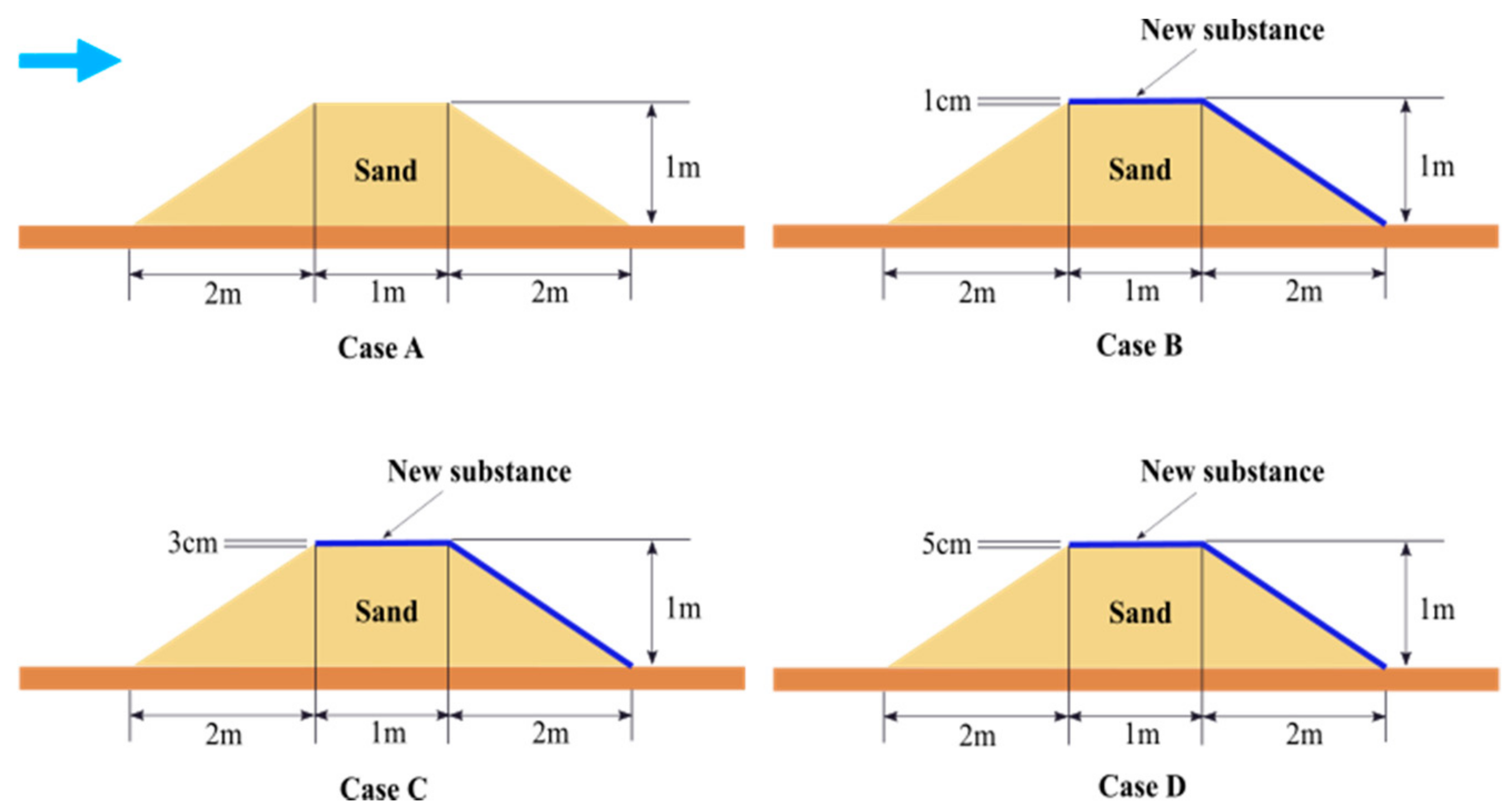
The new substance was fabricated based on a formula (1 g of biopolymer, 10 g of water, and 50 g of sand) provided by the KAIST. In addition, the performance of the proposed levee was verified by applying different thicknesses (e.g., 1, 3, 5 cm) of the new substance (Figure 4). By varying the thickness of the new substance, the retardation effects on a breach over time can be quantified.
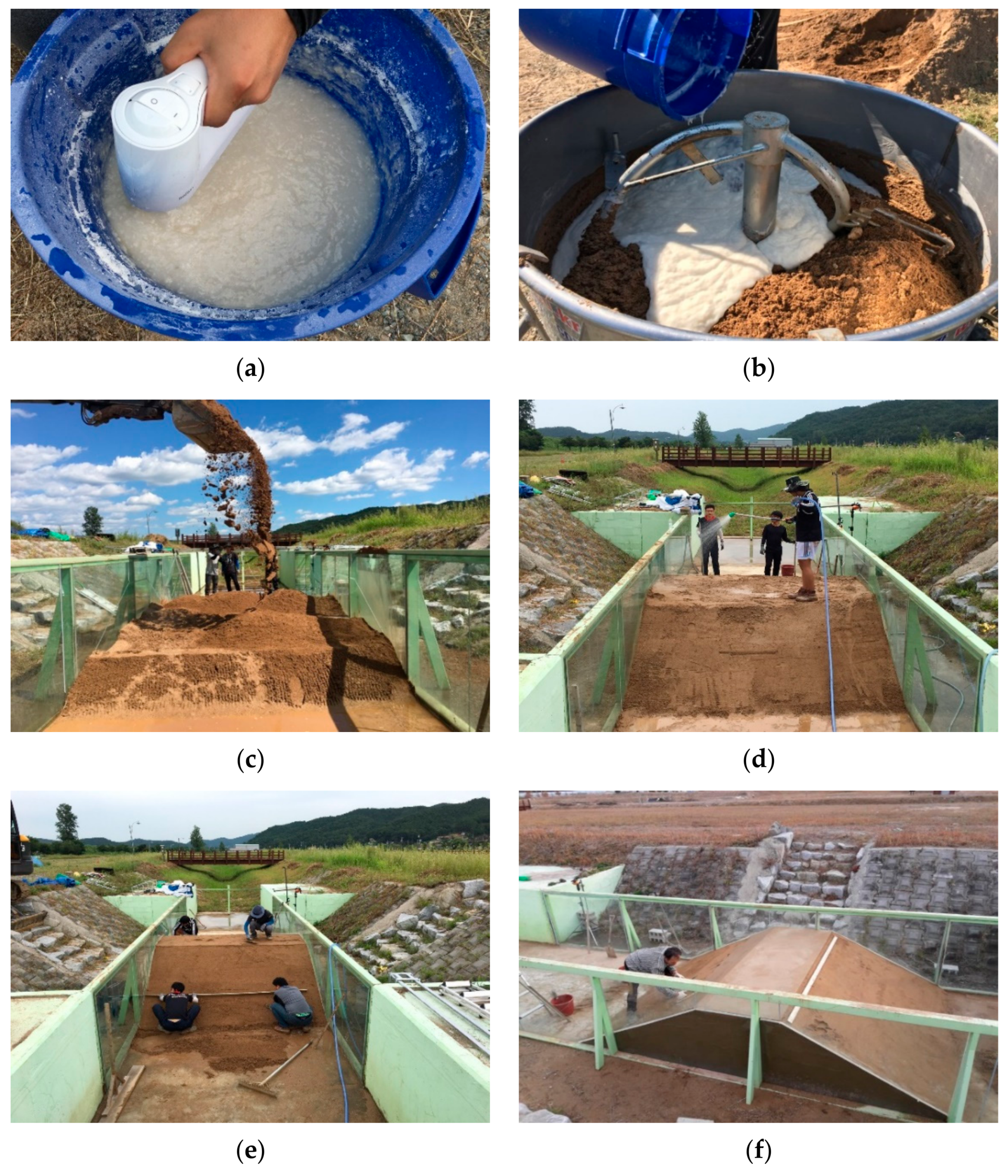
The body of the levee was constructed as follows. Using an excavator (0.2 m3), the sand was dropped from a height of 3 m and was used to build the base of the levee. Next, the levee was built by repeatedly placing water-packed 20 cm layers on top of each other. After building the earthen levee, the biopolymer solution was made by diluting a powder biopolymer with water, and the solution was then mixed with soil. The new substance was then plastered over the levee crest and slope (Figure 5). As a result, the breach mechanisms between the earthen levee and the proposed levee using the new substance were compared.
When the experiment was conducted in Channel A3, the discharge was generally allowed to flow downstream. However, in this experiment, discharge was allowed to flow downstream at a rate of 3 m3/s in Channel A1, and the water level of the outflow pond, which was placed at the downstream end, was then gradually increased to make the water flow back and generate an overflow in Channel A3. This setup was intended to solve the problem in which it takes a considerable amount of time for the discharge to arrive at the downstream end, where the levee model was installed, after passing through about 600 m of Channel A3. Moreover, because a real levee breach flooding an inland area does not cause any drastic decrease in the river, this condition was represented by inducing the flow to originate from the outflow pond, which can store a larger quantity of flow than the upstream channel of A3. The levee inward face was stable under the rising of the water level until overtopping.
3. Results and Discussion
3.1. Comparison of Breaching Processes on Levees along Application of New Substance
The breaching processes of two types of levees were compared to visually analyze the effect of the new substance. The previous studies divided the breaching process of an earthen levee into several phases according to the overflow on the slope and the breach type. During the initial phase, an overflow occurs at the levee crest and the downstream slope is eroded, which generates a small-scale overflow channel. As time goes by, the overflow becomes a step-shaped flow on the downstream slope. Consequently, both the breach width and the overflow quantity increase, which results in an ultimate breach.
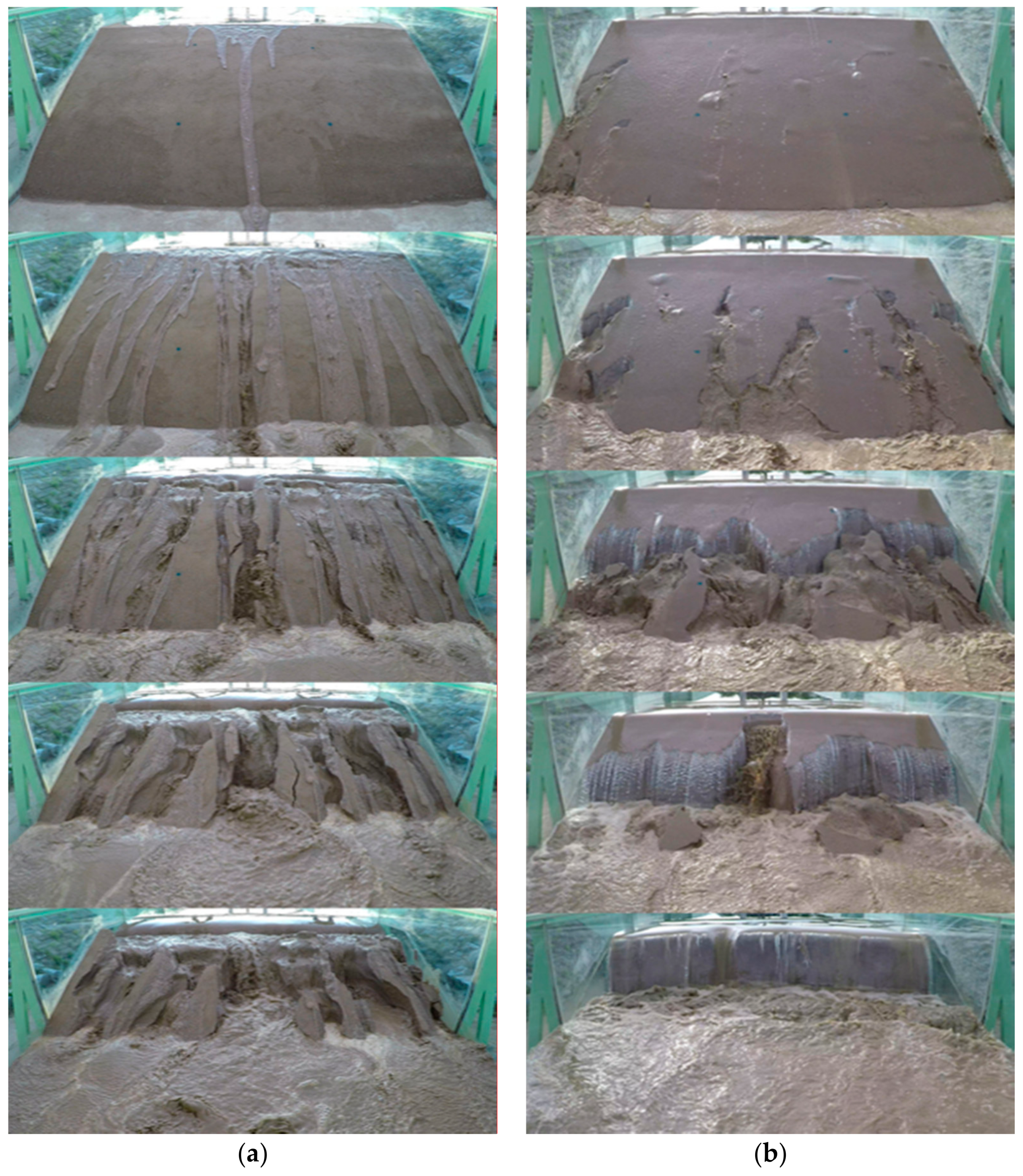
This experiment using an earthen levee also showed that the initial overflow caused the levee crest and slope to be eroded. In other words, the initial flow on the levee slope developed a main flow channel that led to erosion. The continuous flow and the increase in the flow velocity aggravated the streamwise erosion, which resulted in gully erosion with many small gullies. Ultimately, as the amount of overflow increased, the levee crest completely collapsed, and a deep breach surface was generated, which resulted in the maximum breach width owing to a strong shear stress. In the case of the proposed levee using the new substance, the initial overflow caused cracks on some parts of the cover; water penetrated the cracks, resulting in the cover peeling off or inflating. This seemed to be because the new substance was not completely consolidated, or the bio-soil dissolved in the overflow. Accordingly, the new substance needs to be improved by conducting further experiments. A strong vertical flow, which was generated as the resistance to the overflow on the levee crest, caused local scouring at the slope bottom, which resulted in vertical erosion (Figure 6). If the breaching mechanisms of the two types of levees can be compared over the same time, the differences between all breaching processes can be better identified. However, because the earthen levee had a much shorter breaching time than the proposed levee, the breaching process was divided into phases, irrespective of time.
The proposed levee with the new substance showed a totally different breaching pattern than the earthen levee. Although the runoff increased after a certain period of time and every part of the levee was destroyed, unlike the earthen levee where the levee crest started collapsing owing to the initial overflow, the proposed levee did not show any erosion of the levee crest during the initial phase of overflow, but rather gradual erosion starting from the levee toe. The area of erosion tended to significantly decrease over time. The overtopping breach was observed by applying different thicknesses of the new substance. There was only a difference in the amount of collapse, and the overall pattern of the breach was similar. Consequently, because the new substance reduced the peak runoff by retarding the levee breach, it will be effective in reducing flood damage in low-lying areas or preventing secondary damage from a sudden collapse.
3.2. Calculation of the Breaching Rate of a Levee Surface
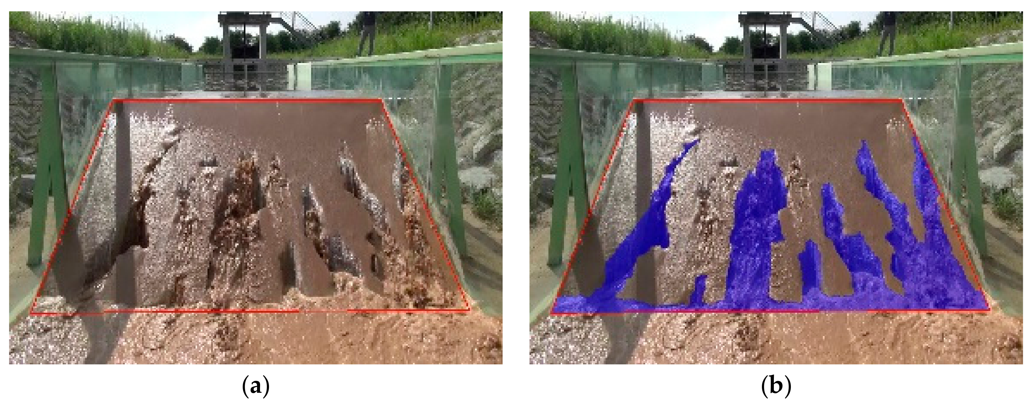
The experimental images taken by the image measuring system were edited and analyzed to verify the scale of the breach over time. Because an image-based analysis is very likely to produce an uncertain or erroneous calculation of the soil runoff caused by an overflowing levee breach, cross-sectional images of a breach on a levee slope were selected and quantitatively analyzed. For the quantitative analysis, the images of the levee slope were captured over time, calibrated, and then digitized to determine the range of the breach (Figure 7).
Graphic software was used for a pixel-based analysis of the target area. In this way, the scales and rates of the levee surface breaches were calculated. Under some experimental conditions, the compaction was not uniform, and an excessive breach was reproduced. To obtain stable results, the experiment was performed twice under each condition. The total number of pixels, which corresponds to the levee slope, was 105,000. Ultimately, the pixel was converted into eroded area as a physical unit. When a breach started, the area lost was calculated every 30 s. The breaching rate was assumed to be 0% at the moment when an overflow occurs. When the surface-breaching rate exceeded 90%, even when the experiment was repeated under the same conditions, the results tended to be inconsistent or the data were unstable. For this reason, any breaching rates over 90% were considered as complete breaches and excluded from the analysis range.
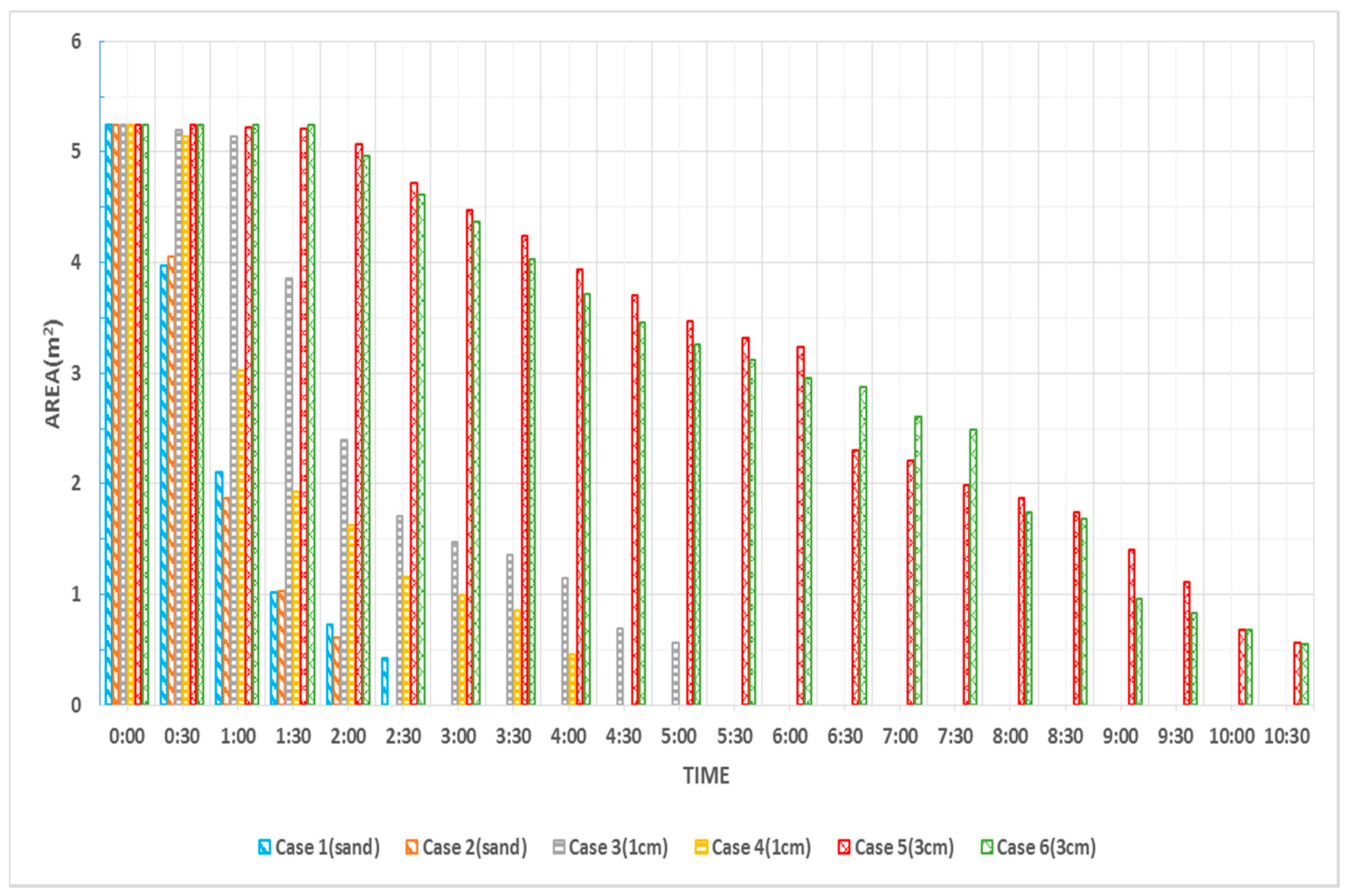
As for the trend in the area reduction over time, which is illustrated in Figure 8, the earthen levee (Cases 1 and 2) showed a drastic decrease in the area simultaneously with the occurrence of an overflow. After 150 s, the area was reduced by over 90%, indicating a complete breach. In Case 3, where a 1 cm thickness of the new substance was applied, the area was maintained for 60 s after an overflow occurred. After 90 s, the area gradually decreased and then showed a drastic decrease until 150 s. Another case of a 1 cm thickness of the new substance (Case 4) showed a reduction in the area at the initial phase of overflow, which differs from the trend in Case 3. This indicates that the percentage of cracks created during the fabrication of the new substance greatly affected the initial breaching rate. The error tended to decrease over time. Compared to Cases 1–4, the 3 cm thickness (Cases 5 and 6) maintained the same area for a while after the occurrence of the overflow. On the whole, the area tended to gradually decrease over time.
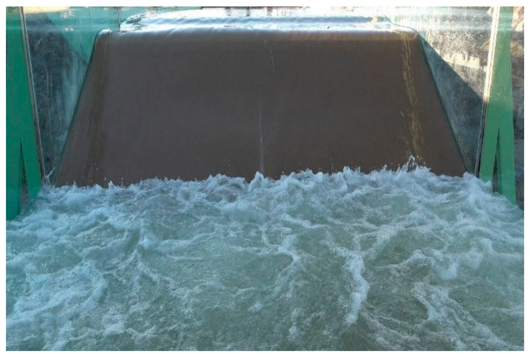
However, when a 5 cm thickness of the new substance was applied, the breach was so excessively retarded that the levee toe began to be inundated with an overflow of water. In other words, the backwater effect affected the experiment with a thickness of 5 cm. For this reason, the performance of the levee could not be analyzed, and this case was excluded (Figure 9). As mentioned above, the experimental setup of this study conversely induced a water flow from the downstream end toward the upstream end. Accordingly, the overflow of water came back to the downstream end before the levee was breached. To evaluate the performance of a levee with the new substance applied at over 5 cm in thickness, the experimental channel needs to be modified accordingly.
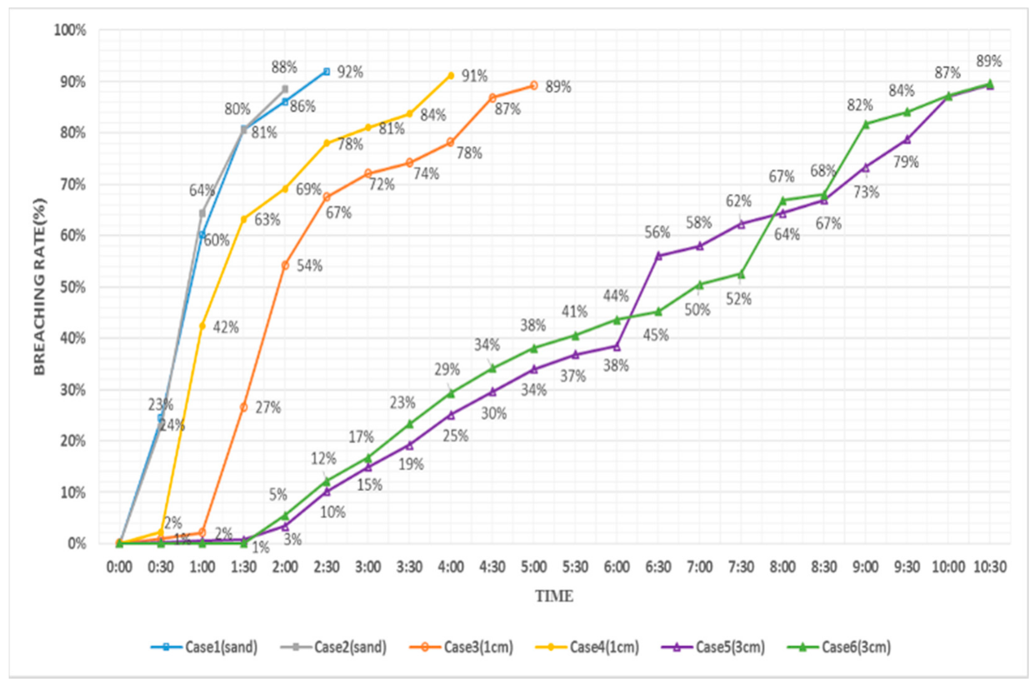
Figure 10 shows the breaching rates of the levee surface over time. Because an overflow occurred, the breaching rates of the earthen levee (Cases 1 and 2) were 23–24% at 30 s, 60–64% at 60 s, 80–81% at 90 s, and 86–92% at 120 s and after. The breaching rates of the levee with 1 cm of the new substance (Cases 3 and 4), with the exception of the initial overflow phase, were 54–69% at 120 s, 67–78% at 150 s, 72–81% at 180 s, 74–84% at 210 s, and 78–91% at 240 s and after. Another levee with 3 cm of the new substance (Case 5 and 6) showed a breaching rate of 5% or less until 120 s, and reached a 50% breaching rate at as late as 390 s. This levee was gradually breached until 630 s, after which the breaching rate exceeded 90%, indicating a complete breach. When the 1 and 3 cm thickness of the new substance were applied, the total breaching times were calculated to be 300 and 630 s, respectively, and based on the above breaching rates. These results indicate that the breach could be retarded by 2 to 4.2 times that of the earthen levee.
The quick initial response and emergence restoration are particularly emphasized in a disastrous situation such as a levee breach. The experiment conducted in this study showed that the earthen levee had an alarming rate of initial breach development, whereas the levee with the new substance was less affected by the initial overflow, and its breach was retarded for a certain period of time. Although a levee breach cannot be fundamentally prevented from causing damage, the result of this study shows that damage can be significantly reduced through appropriate proactive countermeasures.
4. Concluding Remarks
This study conducted a levee breach model experiment by constructing a mid-sized levee model at the Andong River Experiment Center (REC) of the Korea Institute of Civil Engineering and Building Technology. Various imaging devices were used to comparatively analyze the mechanisms of an overflow levee breach. In addition, a pixel-based image analysis method was applied to calculate the scale of breaching on a levee slope over time. In this manner, the performance of the levee with the new substance was verified. The findings of this study can be summarized as follows.
- The levee with the new substance showed a totally different breach mechanism from an earthen levee. The earthen levee experienced a collapse in the interface between the levee crest and slope almost simultaneously with the occurrence of an overflow. In contrast, the levee with the new substance developed a breach from the gradual backward erosion of the levee toe. Moreover, when the overflow breach was observed by applying different thicknesses of the new substance, a difference only occurred in the amount of collapse over time. The overall breaching patterns were similar.
- Based on the breaching rates under overflow conditions, when the new substance was applied, the total breaching times were calculated to be 300 and 630 s, respectively, and the breach of the levee could be retarded between 2 and 4.2 times that of the earthen levee. In particular, the proposed levee was much less affected by the initial overflow than the earthen levee and the breach was retarded for a certain period.
To improve the shortcomings of this study, which were mentioned above, a further study needs to modify the current experimental channel to analyze the performance of a levee with a 5 cm thickness of the new substance. A PIV analysis is also required to derive more precise results and verify the correlation between the inflow velocity and levee breach. Moreover, because a natural river usually has vegetation, its levee might have a significantly different mechanism of erosion and breach than the earthen levee considered in this study. An appropriate method reflecting this fact also seems to be necessary to improve the reliability of the study results.
Author Contributions
D.K. and J.K. designed this study concept and experiments; D.K. and J.K. performed the hydraulic experiments, analyzed the experimental data, and wrote the paper.
Funding
This research was funded by Korea Agency for Infrastructure Technology Advancement, grant number 18AWMP-B114110-03.
Conflicts of Interest
The authors declare no conflict of interest.
References
- Chinnarasri, C.; Jirakitlerd, S.; Wongwises, S. Embankment dam breach and its outflow characteristics. J. Civ. Eng. Environ. Syst. 2004, 21, 247–264. [Google Scholar] [CrossRef]
- Schmocker, L.; Hager, W.H. Overtopping and breaching of dikes—Breach profile and breach flow. In River Flow—Dittrich, Koll, Aberle & Geisenhainer; Bundesanstalt für Wasserbau (BAW): Postfach, Germany, 2010; pp. 515–522. ISBN 978-3-939230-00-7. [Google Scholar]
- Pickert, G.; Weitbrecht, V.; Bieberstein, A. Breaching of overtopped river embankments controlled by apparent cohesion. J. Hydraul. Res. 2011, 49, 143–156. [Google Scholar] [CrossRef]
- Orendorff, B.; AI-Riffai, M.; Nistor, L.; Rennie, C.D. Breach outflow characteristics of non-cohesive embankment dams subject to blast. Can. J. Civ. Eng. 2013, 40, 243–253. [Google Scholar] [CrossRef]
- Hanson, G.J.; Cook, K.R.; Hunt, S.L. Physical Modeling of Overtopping Erosion and Breach Formation of Cohesive Embankments. Am. Soc. Agric. Eng. 2005, 48, 1783–1794. [Google Scholar] [CrossRef]
- Zhang, J.; Li, Y.; Xuan, G.; Wang, X.; Li, J. Overtopping breaching of cohesive homogeneous earth dam with different cohesive strength. Sci. China Ser. E Technol. Sci. 2009, 52, 3024–3029. [Google Scholar] [CrossRef]
- Thornton, C.; Van der Meer, J.; Scholl, B.; Hughes, S.; Abt, S. Testing levee slope resiliency at the new Colorado State University wave overtopping test facility. Coast. Struct. 2011, 2, 167–178. [Google Scholar] [CrossRef]
- Kakinuma, T.; Shimizu, Y. Large-Scale Experiment and Numerical Modeling of a Riverine Levee Breach. J. Hydraul. Eng. 2014, 140, 04014039. [Google Scholar] [CrossRef] [Green Version]
- Kim, J.M.; Park, M.C.; Jo, W.B.; Han, H.S. Seepage Analysis of Weathered Granite Model Embankment Using TDR Sensor. J. Korean Geotech. Soc. 2014, 30, 17–28. [Google Scholar] [CrossRef]
- Kurakami, Y.; Nihei, Y.; Yada, K.; Yamazaki, T.; Yamaguchi, S.; Kawabe, S.; Kikuchi, Y.; Tatsuoka, F. Reinforcing Technology of River Levee for Increasing Resistance against Overflow Erosion. J. Jpn. Soc. Civ. Eng. 2013, 69, 1219–1224. [Google Scholar] [CrossRef]
- Joo, Y.H.; Yeo, C.G.; Lee, S.O. Retardation Effect on the Breach of the Earth Filled Embankment Using the Stiffener during Overtopping. J. Korean Soc. Civ. Eng. 2013, 33, 1377–1387. [Google Scholar] [CrossRef]
- Kim, Y.S.; Jeong, W.S.; Seok, T.R.; Im, A.S. Strength Characteristics of Cemented Sand of Nak-dong River. J. Korean Geo-Environ. Soc. 2006, 7, 43–52. [Google Scholar]
- Carl, M.; Charles, W.; Paul, C.; John, B. Levee Construction and Remediation Using Roller Compacted Concrete and Soil Cement; Rizzo Associates, Inc.: Pittsburgh, PA, USA, 2012. [Google Scholar]
- Wang, Z.; Zhao, B.; Royal, A.C.D. Investigation of Erosion of Cement-Bentonite via Piping. Adv. Mater. Sci. Eng. 2017, 2017, 1762042. [Google Scholar] [CrossRef]
- Guyer, J.P. An Introduction to Soil Cement for Protection of Levees; CreateSpace Independent Publishing Platform: Scotts Valley, CA, USA, 2017. [Google Scholar]
- Caballero, S.; Acharya, R.; Banerjee, A.; Bheemasetti, T.V.; Puppala, A.; Patil, U. Sustainable Slope Stabilization Using Biopolymer-Reinforced Soil. In Geo-Chicago; ASCE Library: Reston, VA, USA, 2016. [Google Scholar] [CrossRef]
- Chang, I.H.; Im, J.Y.; Cho, G.C. Introduction of Microbial Biopolymers in Soil Treatment for Future Environmentally-Friendly and Sustainable Geotechnical Engineering. Sustainability 2016, 8, 251. [Google Scholar] [CrossRef]
Figure 1.
(a) Levee breach on Cheonan River in Korea; (b) road breach and levee scouring in Chungbuk, Korea and (c) levee breach on Kinu River in Japan.
Figure 1.
(a) Levee breach on Cheonan River in Korea; (b) road breach and levee scouring in Chungbuk, Korea and (c) levee breach on Kinu River in Japan.

Figure 2.
(a) View of REC and experimental site and (b) experimental channel (A3).

Figure 3.
Grain size distribution.

Figure 4.
Experimental conditions.

Figure 5.
(a) Mixing with biopolymer and water, (b) mixing with biopolymer solution and sand, (c–e) creating a levee model, and (f) covering with the new substance.
Figure 5.
(a) Mixing with biopolymer and water, (b) mixing with biopolymer solution and sand, (c–e) creating a levee model, and (f) covering with the new substance.

Figure 6.
Breaching pattern (a) in the earthen levee, and (b) in the levee covered with the new substance.
Figure 6.
Breaching pattern (a) in the earthen levee, and (b) in the levee covered with the new substance.

Figure 7.
(a) Image calibration and (b) digitizing of breach range.

Figure 8.
Reduction in the area along experimental cases over time.

Figure 9.
Backwater problem in the case of a 5 cm thickness.

Figure 10.
Breaching rates along experimental cases over time.

© 2018 by the authors. Licensee MDPI, Basel, Switzerland. This article is an open access article distributed under the terms and conditions of the Creative Commons Attribution (CC BY) license (http://creativecommons.org/licenses/by/4.0/).
Share and Cite
MDPI and ACS Style
Ko, D.; Kang, J. Experimental Studies on the Stability Assessment of a Levee Using Reinforced Soil Based on a Biopolymer. Water 2018, 10, 1059. https://doi.org/10.3390/w10081059
AMA Style
Ko D, Kang J. Experimental Studies on the Stability Assessment of a Levee Using Reinforced Soil Based on a Biopolymer. Water. 2018; 10(8):1059. https://doi.org/10.3390/w10081059
Chicago/Turabian StyleKo, Dongwoo, and Joongu Kang. 2018. "Experimental Studies on the Stability Assessment of a Levee Using Reinforced Soil Based on a Biopolymer" Water 10, no. 8: 1059. https://doi.org/10.3390/w10081059
Note that from the first issue of 2016, this journal uses article numbers instead of page numbers. See further details here.