Small Microplastic Sampling in Water: Development of an Encapsulated Filtration Device


Leibniz Institute for Baltic Sea Research Warnemünde (IOW), Seestraße 15, 18119 Rostock, Germany
*
Author to whom correspondence should be addressed.
Water 2018, 10(8), 1055; https://doi.org/10.3390/w10081055
Submission received: 21 June 2018
/
Revised: 20 July 2018
/
Accepted: 2 August 2018
/
Published: 8 August 2018
(This article belongs to the Section Water Quality and Contamination)
Abstract
:A variety of microplastic sampling instrumentation is currently used for water pollution studies. Plankton net-based approaches have been the most adopted techniques for water column and surface sampling. When applied to microplastics (MP) in the lower µm size range these methods, however, introduce non-negligible risks of sample contamination and loss due to instrument and procedure design. Based on the first principles of systems engineering design we have developed a mobile sampling platform for field application that fulfils the needs of producing usable MP samples with a lower size limit of 10 µm using an encapsulated flow-through filtration concept. Here, we explain the requirements, development, and construction of the device for others to replicate and improve.
1. Introduction
The sampling of microplastics (MP) from surface waters or in the water column is dominated by towed net sampling techniques inherited from plankton research. These include, foremost, Manta trawls [1] that skim a film of surface water of constant depth for floating matter and retain the mesh-size-defined particulate filtrate in a cod-end [2,3,4]. Bongo nets, WP-2 nets, as well as special constructions for layered profiling have been applied alike [5,6,7,8]. Single or staggered open sieve constructions, as well as encapsulated flow-through filtration devices are approaches that have been utilised by other studies [9,10,11]. Additionally, sampling of MP has been accomplished by means of density separation in continuous flow centrifuges used in suspended matter analysis [12].
Common for all methods is the extraction of suspended particulate matter from the sampled water compartment. An obtained sample has to be removed from the device and stored for transport in a quantitatively complete manner, while procedural contamination with fibres or particles of synthetic polymers has to be excluded. The assurance of these two conditions is the crux for standard plankton net-based approaches. The equipment itself commonly consists of a variety of plastic polymers, such as monofilament polyamide meshes, synthetic textiles, like ropes, seams, and reinforcing fabrics, for instance, made of spun micro-fibrous polyethylene terephthalate (PET). Frames, connectors, and cod-ends can include hard plastic parts where polyethylene (LDPE or HDPE), polypropylene (PP), or polyvinylchloride (PVC) would be common suspects. Usage-related wear is bound to occur under such setups, i.e., as parts are moving against each other or metals included in the construction. Samples are often exposed to airborne contamination during handling and transfer time on board. Together these drawbacks render plankton nets inadequate for small microplastics (S-MP) sampling, while larger size fractions (L-MP) alone might still be investigated by these techniques with reasonable accuracy. Most studies used mesh sizes between 300 and 390 µm [13], which seems a reasonable cut-off to yield acceptable and meaningful samples under open net sampling conditions, whereas MP below this size would necessitate techniques that appropriately address these constructional vulnerabilities. That it is, however, important to adequately cover the lower microplastic size ranges in surveys that estimate current pollution levels, and has been highlighted by recent research articles and reports [10,11,14], reviews [13], and legislative policy advice [15,16,17]. Typical sources of small MP size fractions, such as tyre wear or intentionally added abrasive MP in products, are named as points of concern by the latter.
The precision of net sampling relies on the volume counting usually done by mechanical flow meters in front of, or inside, the net’s mouth. With pressure building up inside the net due to the tow velocity, and depending on the mouth size and shape, as well as the net and mesh size, the apparent volume passing through the net can vary from what is received by the mechanical counter [18,19]. Another factor, which applies to all mesh-based sampling approaches is the diminishing apparent mesh size with an advancing fill level and clogging of pores [20], leading to increased hydraulic head loss of the unit. Two resulting consequences are the diminished volume flow and a change of the retained particle size spectrum towards smaller sizes.
2. Technical Development
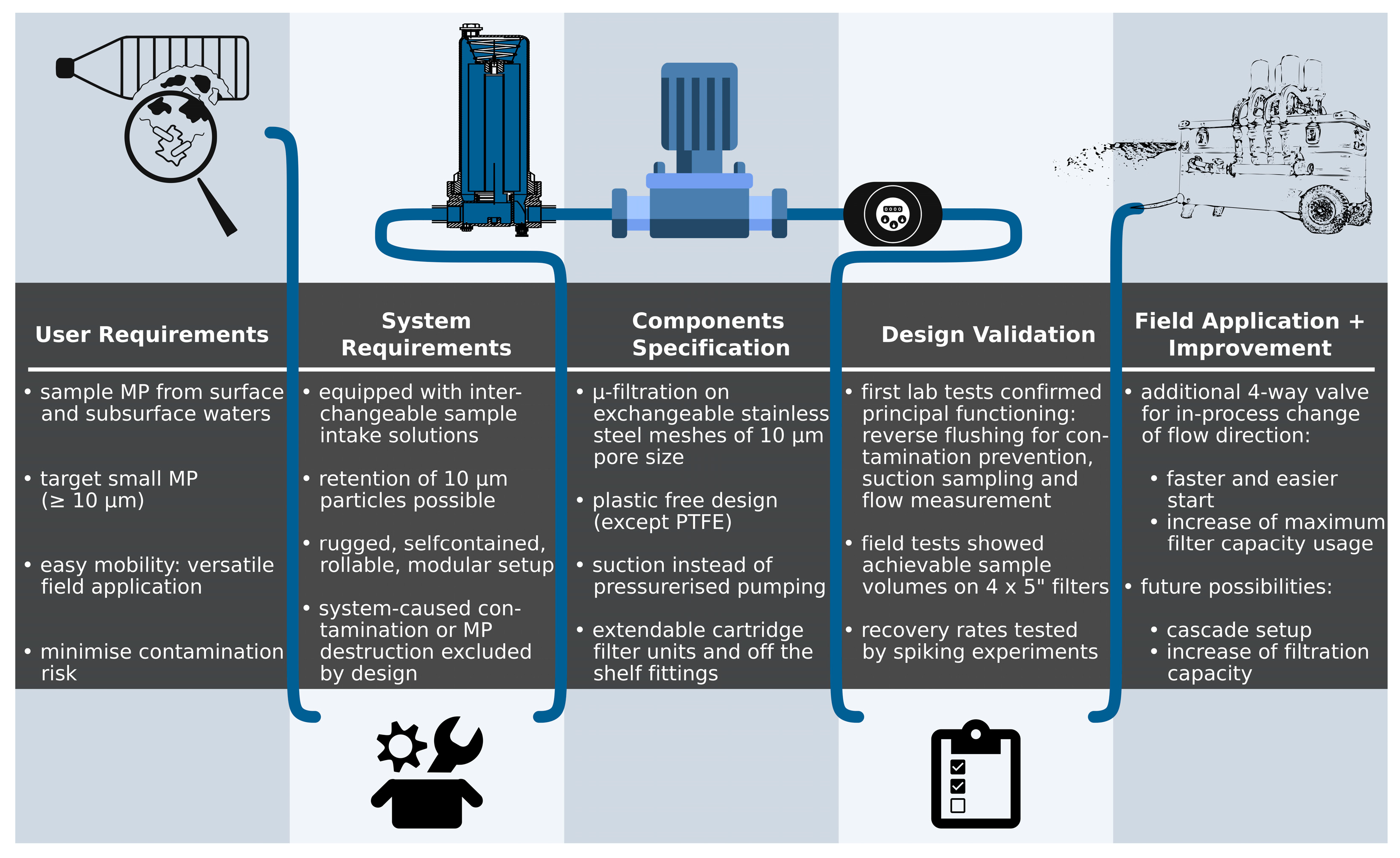
Starting from formulating and narrowing down the problem a user would want to solve with the system we commenced to develop a set of system requirements needed to fulfil the user’s demands. Based on first principles of engineering design a range of component concepts was then evaluated against the criteria set by the user and system requirements in light of achieving the wanted result with the simplest design or lowest number of potential points of failure possible.
The overarching premise of the user in the present case is to be able to sample microplastics of any kind suspended in the water column or on the surface where the lower size limit of 10 µm is the single most influential factor dictating the subsequently determined requirements of contamination prevention and quantitative sample retention. A closed filter design, the avoidance of plastic polymers in the equipment parts that are in contact with the sample, as well as a filtration pump setup operated in suction mode, are seen as the most important constructional features to overcome the problems known from other available sampling equipment described above, which is predominantly used for larger MP. An overview of the development process from user and system requirements, the selected solution and testing results thereof are illustrated in the scheme below (Figure 1).
The device is built in and around a movable aluminium storage container (K 424 XC, Zarges, Weilheim, Germany) which acts as a transport vehicle, an operation platform, and as a container for long-term storage in between sampling campaigns (Figure 2a). To avoid unnecessary exposure to plastic polymers the sample is only in contact with the following materials: metals (i.e., stainless steel, aluminium), silicone in O-rings, and polytetrafluoroethylene (PTFE). The latter is applied as a sealant in ball valves and fittings, as well as an inner lining of the sampling hose (TuFlour Chem PTFE, 32 mm inner diameter, TuDerTechnica Chemours Company, Saccolongo, Italy). The hydraulic setup can be seen in Figure 3. Although PTFE belongs to the synthetic carbon-based thermoplastic polymers it was chosen to facilitate the sample transport with minimised loss due to particles settling out of the flowing liquid and sticking to the walls. For this reason PTFE is excluded from the results if found in the spectroscopic analysis that all samples undergo. Based on the comparably low production volume of PTFE [21], which is ~0.05% of the major commodity plastic types [22], and its high wear resistance and chemical stability, very low, to no, particles are practically expected in environmental samples at the targeted size range ≥10 µm. We argue for, and assume that, the above reasons for the exclusion of PTFE does not introduce any non-negligible error in MP particle concentrations measured. It should be noted that if smaller sizes are targeted this assumption should be critically evaluated as PTFE has found applications as micrometre-sized particles in dry lubrication aerosol sprays (0.1–1 µm) [23] and as nano-particles in surface coatings [24].
The sampling which has a 32 mm inner diameter is built in two parts of ca. 7 m length each that can be connected by a metal quick coupling (CamLock fittings according to EN14420-7, by Schwer Fittings GmbH, Denkingen, Germany) to give flexibility for varying sampling site conditions. The ends of the sampling hose are likewise equipped with quick connectors where one side mounts to a distributor for four individual filtration lines, and the other one holding a mouthpiece of choice depending on the sampled compartment (Figure 3).
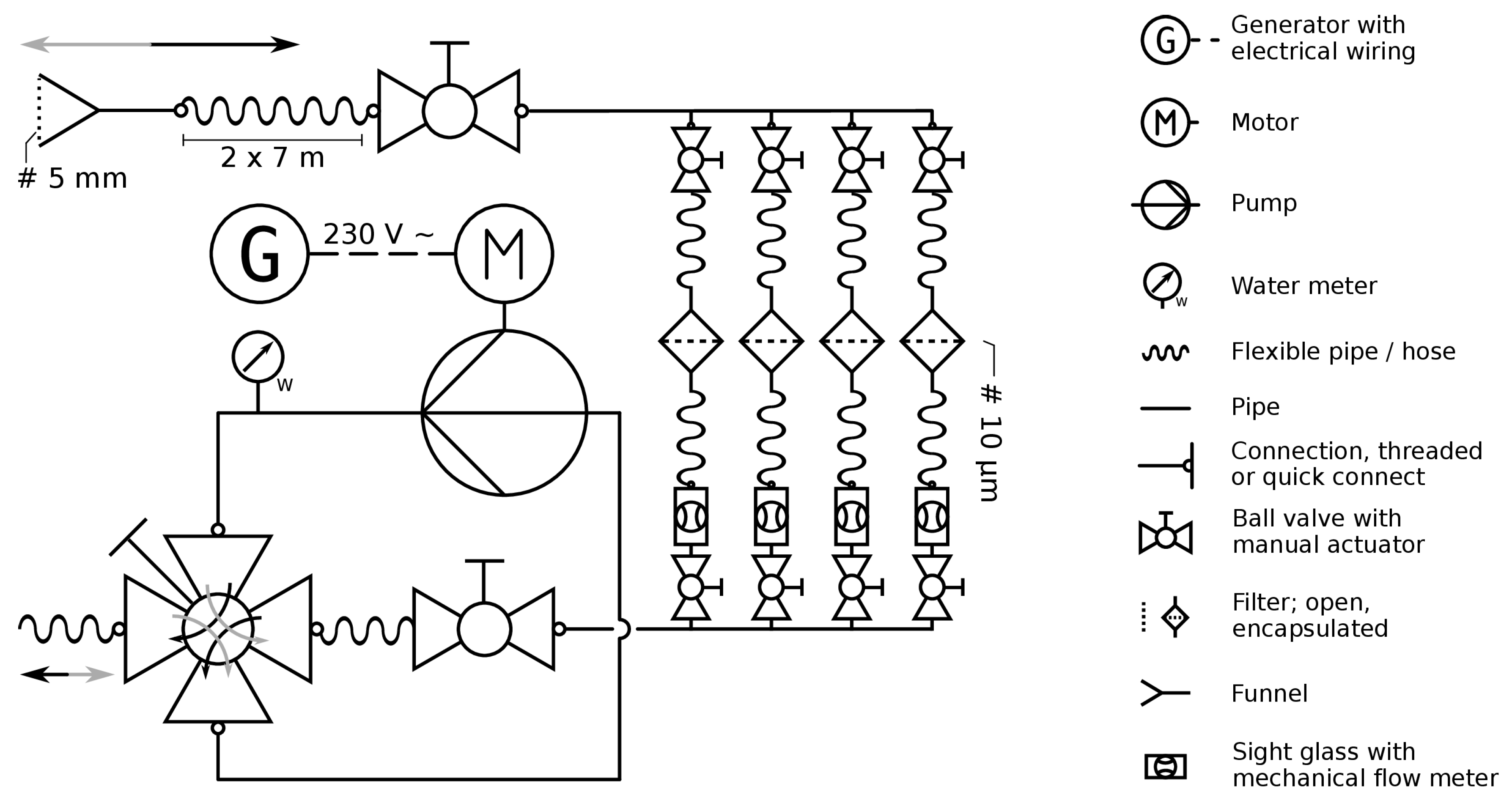
Past the distributor the sample is retained as the flow traverses through stainless steel cartridge filters at 10 µm mesh size (01WTGD, with 124 mm (4 7/8”) filters, Wolftechnik Filtersysteme GmbH and Co. KG, Weil der Stadt, Germany). The individual filter elements consist of a perforated inner support sheet metal and a top and bottom plate which confine and hold the mesh screen without any adhesive or cementing material. They are held in place tight inside the unit by a screw pole and a stainless steel tightening cap which presses against PTFE ring seals on each side of the double open-end (DOE) element (see also Figure 2b). The combined filter surface area amounts to 975 cm2. Larger filter elements, such as cartridges of 5, 10 or 20 inches could be mounted together with their corresponding housings. This way the total filter area and, hence, the sample volume capacity, can be increased, however, at the cost of more demanding sample processing and larger equipment to be handled. At the outlet after each filter housing a see-through observation chamber with a built-in flow rate meter gives an indication of the degree of blocking of the respective filter. The four lines enter into a collector opposite the distributor which passes the water on towards the pump. We applied a centrifugal jet pump (type Jimg 12, Tellarini Pompe S.n.c., Lugo, Italy) which was chosen for its properties of high capacity of nominal 3.6 m3 h−1 and wet self-priming functionality with up to 8 m elevation. It has no dry self-priming capability, meaning that an initial fill is needed before a flow can be established. An impeller pump could be used instead to overcome this necessity, however, at the cost of higher wear during operation and reduced resistance to dry running break down. The addition of a four-way valve with an double L-shaped bore (also referred to as the X port valve) between the two pump ports in one axis, and the collector outlet and discharge port along the other, creates the possibility to promptly reverse the direction of the flow through the system. This allows for an easy priming of the pump and, at the same time, enables a reverse flushing of the filter parts after the cartridge units have been assembled and closed for operation at a sampling site. The flushing procedure eliminates potential airborne contamination which might have settled on the filters during mounting and is used to rinse out the distributor and sampling hose to avoid site cross-contamination in consecutive activities on a sampling campaign.
3. Experimental Work and Validation Results
The volume that passed the system is accurately measured using a standard sanitary water meter (8ZR100, Zenner International, Saarbrücken, Germany). These devices are calibrated according to local legislation, i.e., for the EU, following Annex III of the Directive 2014/32/EU demanding volume measurement errors of 2% or less [25]. Generally, the functioning of such water meters is based on an impeller rotating as water passes by and driving a counter on the display side. Due to this design it has to be assumed that water–air mixtures can lead to positive, as well as negative, misreading. The former may occur as air-enriched water will take up a larger volume compared to the same water when degassed and, thus, move the counter further, while the latter can be a result of temporary break-down of the flow inside the impeller chamber due to high air entrainment with the remaining passing water volume being too small to adequately spin the rotor. Cases of water–air mixtures could be expected during field sampling due to short-term accidental air intake or leaks in the system. To quantify the error margin two setups were tested under laboratory conditions: a known water volume was passed through the device where, in one case, a deliberate leak was introduced by a thin silicone tubing inserted into the otherwise submerged sample intake, fixed with the open end above the water surface, creating a minor air entraining situation. In the other case the mouth of the sample intake itself was held only half submerged creating a repeatedly breaking down and recovering flow. Readings after the small air entrainment differed from the real water volume by up to 5%, while the larger air intake resulted in ca. 20% difference. The perpetual submersion and a proper check for tightness of all connections are, therefore, a requirement for accurate volume readings. An addition of an air separator prior to the volume meter could be a way to overcome this limitation.
In order to evaluate MP retention we ran the filter system by feeding tap water which had been pre-filtered on 10 µm and inserted pre-counted batches of 1000 pieces per replicate (n = 3) of light red polyamide particles (PA6, fine pre-production nurdles). The cylindrical granules had an average size of 450 and 480 µm in length and diameter, respectively. After each run the filter set was removed and handled in exactly the same way as environmental samples would have been processed. The recovered particles were quantified under a stereomicroscope using a Bogorov counting chamber (custom build at own scientific workshop facility). The achieved recovery rate for the three independent replicates averaged 98.9% with a standard deviation of 0.89%.
From first applications in field studies we are able to draw some conclusions on the functioning of the sampling system and provide a proof of principle. Most remarkably, however, not surprisingly, the achievable sample volumes varied vastly depending on the suspended matter loadings. While turbid river waters in agricultural areas during spring snow melt often allowed ca. 200–300 L to be sampled on one set of filters (location and time data of field applications where achievable sample volumes have been estimated from are provided in the supplementary material: Table S1), clearer rivers were on the order of 200 to 700 L total sample volume. The premature clogging in turbid river waters is attributed to the settling of fine sediment load in between the stainless steel webbing of the filters.
This effect could be counteracted by choosing a larger mesh size (if compatible with the respective research question) or increasing the deployed filter surface area. Wastewater treatment plant (WWTP) outflow water could be sampled with ca. 600 L to 1 m3, tested at two facilities. The latter was chosen as the desired maximum volume per sample and was not caused by clogging of the filters. In coastal marine waters during winter conditions up to 2 m3 have been sampled before the filter capacity was exhausted.
The sampling time may vary due to water quality and terrain. Up to four sampling stations per day are deemed realistic for a two- or three-person field work team.
4. Discussion and Conclusions
We have developed a water sampling system to be used for environmental surveys of microplastic contamination in surface and sub-surface waters. The major problems addressed with this new development are the difficulty of sampling small-sized MP from water and the contamination risk associated. The benefits in the current stage of development can be summarised as:
- Minimised contact to plastic polymers: only PTFE and non-plastic materials;
- Closed design: minimised sample exposure time; and
- No handling on site required: samples are transported in the replaceable unit of the cartridge filters.
The primary intended use-case is the sampling of S-MP (i.e., the size fraction below 300 µm) in source areas, such as rivers, inland wet areas and drainages, WWTP outflows, and estuarine and near-shore coastal waters. L-MP will, by design, also be sampled quantitatively, however, the nominal sample volume of 1 m3 is too low to allow for statistically sound analysis as typical abundances are often below one particle per m3 and methods of higher volume throughput are needed. On the contrary, open ocean surface concentration data from studies which included S-MP were frequently on the order of 100–200 m−3 [10,11], which implies that sample sizes of 1 m3 may produce meaningful data under these conditions. In Table 1 we summarise the advantages and drawbacks of the current and alternative methods.
On-going work will improve the system in terms of usability and achievable sample volumes. In the current state we applied the four filtering channels in parallel for maximised sampling capacity. If a lower sample volume is acceptable or if longer filter cartridges are used and operated separately, the system seems suitable for streamlined sampling of replicates, e.g., in short time intervals or at different positions at the same location. A recent study on MP monitoring underpinned the importance of replicated sampling throughout a river cross-section [5]. This is just one possible modification to adapt the system to specific sampling scenarios and we encourage others to contact us for requests or comments and to replicate or improve upon the suggested design.
Supplementary Materials
The following are available online at https://www.mdpi.com/2073-4441/10/8/1055/s1, Table S1. Locations, dates and sample volumes from a first sampling campaign in the Warnow river system (Mecklenburg-Vorpommern, Germany).
Author Contributions
Conceptualization: R.L., M.L.; Methodology: R.L.; Validation: R.L., M.L.; Formal Analysis: R.L.; Investigation: R.L.; Resources: M.L.; Data Curation: R.L.; Writing—Original Draft Preparation: R.L.; Writing—Review and Editing: M.L.; Visualization: R.L., M.L.; Supervision: M.L.; Project Administration: M.L.; Funding Acquisition: M.L.
Funding
This research was funded by BmBF project MicroCatch_Balt, grant number 03F0788A.
Acknowledgments
The authors gratefully appreciate the help of L.M., J.G., A.T. and K.E. in conducting laboratory test runs and field work trials of the system. For constructional assembly we thank K.R., and for fruitful discussions on technical practicalities, G.G., C.L. and M.L.
Conflicts of Interest
The authors declare no conflict of interest. The funders had no role in the design of the study; in the collection, analyses, or interpretation of data; in the writing of the manuscript, and in the decision to publish the results.
References
- Brown, D.; Cheng, L. New Net for Sampling the Ocean Surface. Mar. Ecol. Prog. Ser. 1981, 5, 225–227. [Google Scholar] [CrossRef]
- Tamminga, M.; Hengstmann, E.; Fischer, E.K. Microplastic analysis in the South Funen Archipelago, Baltic Sea, implementing manta trawling and bulk sampling. Mar. Pollut. Bull. 2018, 128, 601–608. [Google Scholar] [CrossRef] [PubMed]
- Gewert, B.; Ogonowski, M.; Barth, A.; MacLeod, M. Abundance and composition of near surface microplastics and plastic debris in the Stockholm Archipelago, Baltic Sea. Mar. Pollut. Bull. 2017, 120, 292–302. [Google Scholar] [CrossRef] [PubMed]
- Setälä, O.; Magnusson, K.; Lehtiniemi, M.; Norén, F. Distribution and abundance of surface water microlitter in the Baltic Sea: A comparison of two sampling methods. Mar. Pollut. Bull. 2016, 110, 177–183. [Google Scholar] [CrossRef] [PubMed]
- Liedermann, M.; Gmeiner, P.; Pessenlehner, S.; Haimann, M.; Hohenblum, P.; Habersack, H. A Methodology for Measuring Microplastic Transport in Large or Medium Rivers. Water 2018, 10, 414. [Google Scholar] [CrossRef]
- Norén, F.; Naustvoll, L. Survey of Microscopic Anthropogenic Particles in Skagerrak; N-Research, Lysekil & Institute for Marine Research: Flødevigen, Sweden, 2010. [Google Scholar]
- Reisser, J.; Slat, B.; Noble, K.; du Plessis, K.; Epp, M.; Proietti, M.; de Sonneville, J.; Becker, T.; Pattiaratchi, C. The vertical distribution of buoyant plastics at sea: An observational study in the North Atlantic Gyre. Biogeosciences 2015, 12, 1249–1256. [Google Scholar] [CrossRef]
- Leslie, H.A.; van der Meulen, M.D.; Kleissen, F.M.; Vethaak, A.D. Microplastic Litter in the Dutch Marine Environment—Providing Facts and Analysis for Dutch Policymakers Concerned with Marine Microplastic Litter; Deltares: Amsterdam, The Netherlands, 2011. [Google Scholar]
- Schmidt, L.K.; Bochow, M.; Imhof, H.K.; Oswald, S.E. Multi-temporal surveys for microplastic particles enabled by a novel and fast application of SWIR imaging spectroscopy—Study of an urban watercourse traversing the city of Berlin, Germany. Environ. Pollut. 2018, 239, 579–589. [Google Scholar] [CrossRef] [PubMed]
- Desforges, J.P.W.; Galbraith, M.; Dangerfield, N.; Ross, P.S. Widespread distribution of microplastics in subsurface seawater in the NE Pacific Ocean. Mar. Pollut. Bull. 2014, 79, 94–99. [Google Scholar] [CrossRef] [PubMed]
- Enders, K.; Lenz, R.; Stedmon, C.A.; Nielsen, T.G. Abundance, size and polymer composition of marine microplastics ≥10 μm in the Atlantic Ocean and their modelled vertical distribution. Mar. Pollut. Bull. 2015, 100, 70–81. [Google Scholar] [CrossRef] [PubMed]
- Leslie, H.A.; Brandsma, S.H.; van Velzen, M.J.M.; Vethaak, A.D. Microplastics en route: Field measurements in the Dutch river delta and Amsterdam canals, wastewater treatment plants, North Sea sediments and biota. Environ. Int. 2017, 101, 133–142. [Google Scholar] [CrossRef] [PubMed]
- Hidalgo-Ruz, V.; Gutow, L.; Thompson, R.C.; Thiel, M. Microplastics in the marine environment: A review of the methods used for identification and quantification. Environ. Sci. Technol. 2012, 46, 3060–3075. [Google Scholar] [CrossRef] [PubMed]
- Norén, F. Small Plastic Particles in Coastal Swedish Waters; N-Research: Lysekil, Sweden, 2007. [Google Scholar]
- Communication from the Commission to the European Parliament, the Council, the European Economic and Social Committee and the Committee of the Regions: A European Strategy for Plastics in a Circular Economy; European Union: Brussels, Belgium, 2018.
- United Nations Environment Programme (UNEP). Draft resolution on marine litter and microplastics. In Proceedings of the United Nations Environment Assembly, Nairobi, Kenya, 5 December 2017. [Google Scholar]
- Peter, J.K. Marine Plastic Debris and Microplastics-Global Lessons and Research to Inspire Action and Guide Policy Change; United Nations Environment Programme: Nairobi, Kenya, 2016. [Google Scholar]
- Hernroth, L. Sampling and filtration efficiency of two commonly used plankton nets. A comparative study of the Nansen net and the Unesco WP 2 net. J. Plankton Res. 1987, 9, 719–728. [Google Scholar] [CrossRef]
- Smith, P.E.; Counts, R.C.; Clutter, R.I. Changes in filtering efficiency of plankton nets due to clogging under tow. ICES J. Mar. Sci. 1968, 32, 232–248. [Google Scholar] [CrossRef]
- Evans, M.S.; Sell, D.W. Mesh size and collection characteristics of 50-cm diameter conical plankton nets. Hydrobiol. 1985, 122, 97–104. [Google Scholar] [CrossRef]
- Polytetrafluoroethylene (PTFE)—A Global Market Overview. Available online: https://www.reportlinker.com/p03769747/Polytetrafluoroethylene-PTFE-A-Global-Market-Overview.html (accessed on 2 July 2018).
- Plastics Europe Plastics—the Facts 2017—An Analysis of European Plastics Production, Demand and Waste Data; Plastics Europe (the Association of Plastics Manufacturers in Europe) and EPRO (the European Association of Plastics Recycling and Recovery Organisations): Brussels, Belgium, 2017.
- Weißbach, W.; Dahms, M.; Jaroschek, C. Werkstoffkunde; Springer Fachmedien Wiesbaden: Wiesbaden, Germany, 2015. [Google Scholar]
- Basu, B.J.; Dinesh Kumar, V. Fabrication of Superhydrophobic Nanocomposite Coatings Using Polytetrafluoroethylene and Silica Nanoparticles. ISRN Nanotechnol. 2011, 2011, 1–6. [Google Scholar] [CrossRef]
- 2014/32/EU of the European Parliament and of the Council of 26 February 2014 on the Harmonisation of the Laws of the Member States Relating to the Making Available on the Market of Measuring Instruments (Recast); European Union: Brussels, Belgium, 2014.
Figure 1.
Development of the sampling device from requirements design to field application.

Figure 2.
Field assembled configuration of the sampling device: (a) overview of the system during sampling; (b) the 10 µm cartridge modules in closed housing, opened and partly covered with sample; (c) inlet options for water column sampling applied at a waste water treatment plant (WWTP) outlet; and (d) water surface sample intake by aluminium funnel applied on board a boat.

Figure 3.
Piping and instrumentation diagram (P&ID) for the microplastic water sampler. Black arrows indicate main flow direction through the system during sampling. Grey arrows show operation in reverse flushing mode.
Figure 3.
Piping and instrumentation diagram (P&ID) for the microplastic water sampler. Black arrows indicate main flow direction through the system during sampling. Grey arrows show operation in reverse flushing mode.


Table 1.
Summarising comparison of properties, advantages, and limitations of the presented method and two alternative approaches. Costs are denoted as relative estimates ranging from “+” (lowest costs) to “+++” highest costs as actual costs may vary depending on supplier and chosen design specifics.
| Criterion | Encapsulated Flow-through Device (Present System) | Plankton Nets | Continuous Flow Centrifuge |
|---|---|---|---|
| Compartment | Surface and water column | Surface and water column | Surface and water column |
| Primary sampling zone | Rivers, wetland drainages, WWTP outflows, small lakes/ponds | Open ocean, coastal waters/estuaries, large lakes | Rivers, wetland drainages, WWTP outflows, small lakes/ponds |
| Additional sampling zone, suitable to limited extent | Coastal waters/estuaries, open ocean, larger lakes | Large rivers | Coastal waters/estuaries, open ocean, larger lakes |
| Recommendable size range focus | ≥10 µm | ≥300 µm | Any |
| Targeted MP types | Any | Any | HD-MP * |
| One-time expenses | ++ | + | +++ |
| Running costs | + | +++ if ship time is required + if applied from bridge in streams | + |
| Major advantages | S-MP can reliably be sampled with minimized contamination risk | High volume capacity and ease of use | Size independent sampling (no filtration) |
| Major limitations | Lower sample volume capacity e.g., 1 m3, might be too low for L-MP statistical analysis | Not practical for S-MP due to open design and higher contamination risk Ship time required (except for rivers) | LD-MP ** is not sampled by design Large equipment restricts sampling site access and handling requires trained personnel |
| References of method application | [10,11], present study | [2,3,4,5,6,7,8] | [12] |
* = high density polymers (i.e., denser than water); ** = low density polymers (i.e., lighter than water).
© 2018 by the authors. Licensee MDPI, Basel, Switzerland. This article is an open access article distributed under the terms and conditions of the Creative Commons Attribution (CC BY) license (http://creativecommons.org/licenses/by/4.0/).
Share and Cite
MDPI and ACS Style
Lenz, R.; Labrenz, M. Small Microplastic Sampling in Water: Development of an Encapsulated Filtration Device. Water 2018, 10, 1055. https://doi.org/10.3390/w10081055
AMA Style
Lenz R, Labrenz M. Small Microplastic Sampling in Water: Development of an Encapsulated Filtration Device. Water. 2018; 10(8):1055. https://doi.org/10.3390/w10081055
Chicago/Turabian StyleLenz, Robin, and Matthias Labrenz. 2018. "Small Microplastic Sampling in Water: Development of an Encapsulated Filtration Device" Water 10, no. 8: 1055. https://doi.org/10.3390/w10081055
Note that from the first issue of 2016, this journal uses article numbers instead of page numbers. See further details here.